


6 6
Section 2 – Operation
2.1 KNOW THE GENERATOR
Read the Owner’s Manual and Safety Rules before operating this
generator.
Compare the generator to Figures 4 through 6 to become familiarized with
the locations of various controls and adjustments. Save this manual for
future reference.
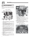
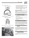
Figure 4 - Control Panel
10
10
1 17 13
2
3
4
56
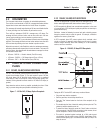
1. 12 Volt DC, 10 Amp Receptacle – This receptacle allows the
capability to recharge a 12 volt DC storage battery with provided
battery charge cables.
2. 120 Volt AC, 20 Amp, Duplex Receptacle – Supplies electrical
power for the operation of 120 Volt AC, 20 Amp, single-phase, 60
Hz electrical lighting, appliance, tool and motor loads.
3. 120 Volt AC, 20A Duplex GFCI Receptacle – Supplies ground fault
protected electrical power for operation of 120 volt AC 20 amp,
single-phase, 60 Hz electric lighting, appliances, tools and motor
loads.
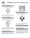
4. 120 Volt AC, 30 Amp Locking Receptacle – Supplies electrical
power for the operation of 120 Volt AC, 30 Amp, single-phase, 60
Hz electrical lighting, appliance, tool and motor loads.
5. 120/240 Volt AC, 30 Amp Locking Receptacle – Supplies electrical
power for the operation of 120 and/or 240 Volt AC, 30 Amp, single-
phase, 60 Hz, electrical lighting, appliance, tool and motor loads.
6. 120/240 Volt AC, 50 Amp Receptacle (17.5kW, Located on
underside of control panel)– Supplies electrical power for the
operation of 120/240 Volt AC, 50 Amp, single-phase, 60 Hz, welder
or motor loads.
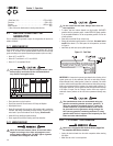
7. Air Cleaner – Filters intake air as it is drawn into the engine.
8. Choke Knob – Used when starting a cold engine.
9. Winter/Summer Valve – See “Cold Weather Operation/De-icer”
section.
10. Circuit Breakers (AC) – Each receptacle is provided with a push-
to-reset circuit breaker to protect the generator against electrical
overload. (50 amp uses toggle reset)
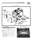
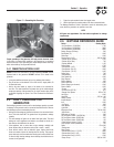
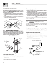
Figure 5 - Generator Controls
11. Fuel Tank – Tank holds 16 U.S. gallons of fuel.
12. Grounding Lug – Ground the generator to an approved earth ground
here. See "Grounding the Generator" for details.
13. Idle Control Switch – The idle control runs the engine at normal
(high) speeds when there is an electrical load present and runs the
engine at idle (low) speeds when a load is not present.
14. Start/Run/Stop Switch – Controls the operation of the generator.
15. Oil Fill – Use this point to add oil to engine.
16. Fuse - 10 Amp (Located at rear of control panel) – Protects the DC
control circuit from overload. If this fuse element has melted open
the engine will not be able to crank and start.
17. Hourmeter - Tracks hours of operation.
Figure 6 - Engine Control Panel
14
8
9
7
15
12
11