


9
Section 4
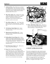
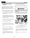
5. Ammeter (Figure 4-1). Indicates the condition of
the charging system. When the engine is running
the needle should be at the positive end of the meter.
If the needle is on the negative end of the meter, this
indicates a discharge condition and the machine
should be taken in for service.
6. Hour Meter (Figure 4-1). Indicates the number
of hours the engine has been operated. It operates
whenever the ignition switch key is in the ON
position. It can be used to keep track of
maintenance intervals and the amount of time
required to perform various tasks.
7. Fuse Holders (Figure 4-1). Two 20-amp fuses
protect the mowers electrical system. To replace
fuses, pull fuse out of the socket and install a new
fuse.
8. Left Steering Control (Figure 4-1). Used to
control the mower's left wheel when traveling
forward or reverse.
9. Right Steering Control (Figure 4-1). Used to
control the mower's right wheel when traveling
forward or reverse.
10. Parking Brake Control (Figure 4-1). Used to
engage and disengage the parking brakes and also
used to lock the cutter deck from tilting up to high
while traveling. Pull the lever back and lock in place
to engage the parking brakes. Push the lever
forward to disengage the parking brakes and engage
the deck tilt lock.
11. Fuel Tank Gauges (Figure 4-1). Indicates the
amount of fuel in the fuel tanks.
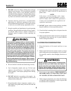
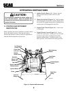
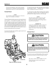
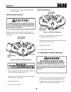
12. Dump Valve Control Levers (Figure 4-2).
Located under the seat, on the hydraulic pumps,
used to free-wheel the mower. Rotating the levers
clockwise until they stop allows the unit to move
under hydraulic power. The levers must be in this
position during operation of the mower. Rotating
the levers counterclockwise, one turn, allows the
mower to be moved by hand (free-wheeling).
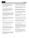
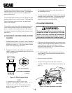
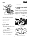
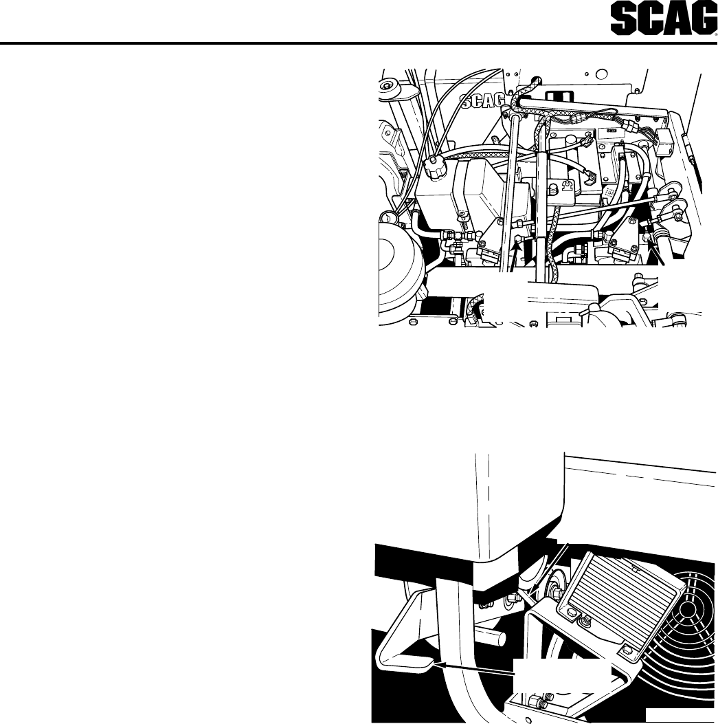
13. Blower Belt Release (Figure 4-3). This lever is
used to release the belt tension and allow the blower
belt to be removed when the cutter deck is setup as
either a mulching or a side discharge deck.
Figure 4-2 Dump Valves Location
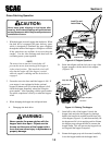
4.2 SAFETY INTERLOCK SYSTEM
The mower is equipped with a safety interlock system
that prevents the engine from starting unless the deck
drive is disengaged and the speed control is in neutral and
the parking brake is engaged. The interlock system shuts
off the engine if the operator leaves the seat with the
speed control in the neutral position and the parking
brake is not engaged and/or the cutter blades are
engaged. It will also shut the engine off if the cutter
deck drive is engaged and the hopper is raised.
Figure 4-3 Blower Belt Release
Blower Belt
Blower Belt
Release Pedal
SCR 2K BBR
Right
Dump
Valve
SCR 2K DVL
Left
Dump
Valve