


10
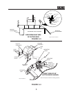
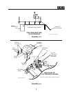
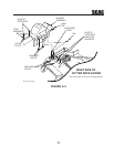
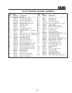
3. When installing this grass catcher on a machine
with a serial number below 8619999, you will
need to remove the discharge baffle from the
bottom of the cutter deck. See Figure 5-2.
Replace the discharge baffle with the new baffle
provided with this grass catcher. Secure using
the following hardware:
(1) 04001-12 Hex Head Bolt 5/16-18 x 1-3/4"
(1) 04001-09 Hex Head Bolt 5/16-18 x 1"
(3) 04040-15 Flatwasher
(3) 04021-10 Nut, Elastic Stop 5/16-18
When installing this grass catcher on an
Advantage deck, install the front baffle to the
cutter deck. See Figure 5-2. Secure using the
following hardware:
(2) 04017-05 Bolt, Hex Head 1/4-20 x 3/4"
(2) 04019-02 Nut, Serrated Flange 1/4-20
(2) 04003-23 Bolt, Carriage 3/8-16 x 1"
(2) 04041-07 Flatwasher
(2) 04021-09 Nut, Elastic Stop 3/8-16
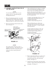
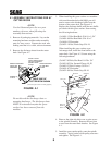
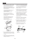
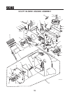
4. Remove the right side belt cover to gain access
to the spindle assembly. Remove the two front
u-nuts from the cutter deck bracket. See Figure
5-1, Page 9.
5. Install the grass catcher pulley onto the spindle
assembly. Apply loctite to both pulley setscrews
and tighten. See Figure 5-1.
FIGURE 5-2
Discharge
Baffle
04003-23
04017-05
04019-02
04041-07
04041-07
04021-09
04001-09
04040-15
04021-10
04021-09
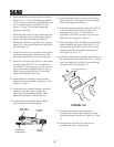
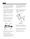
6. Install the blower mounting bracket to the deck
using 1/2-13 x 1-1/2" hex head bolts (p/n 04001-
71), 1/2" spring lockwashers (p/n 04030-06), and
1/2-13 elastic stop nuts (p/n 04021-07). See
Figure 5-3, Page 11. Do not fully tighten the
hardware at this time.
7. Install the new belt cover from the cutter deck to
the blower mounting bracket and secure with
one of the original belt cover plastic wing nuts.
8. Install the catch plate (p/n 423297) to the blower
assembly using 3/8-16 x 1-1/4" carriage bolts
(p/n 04003-11) facing upward. See Figure
5-3, Page 11. Secure with 3/8" spring
lockwashers (p/n 04030-04) and 3/8-16 elastic
stop nuts (p/n 04021-09). Do not fully tighten the
hardware at this time.
9. Install the blower assembly to the mounting
bracket and secure with the mounting pin and
large hair pin. See Figure 5-3, Page 11.
10. Align the blower assembly with the discharge
opening of the cutter deck. Tighten the
hardware for the mounting bracket. Then
tighten the hardware for the catch plate.
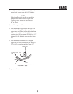
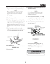
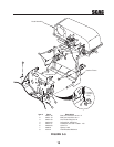
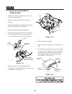
11. Install the belt to the spindle pulley. When
replacing the belt, see figure below.
FRONT SIDE
IDLER PULLEY
BACK SIDE
IDLER PULLEY
BLOWER
PULLEY
SPINDLE
PULLEY