


8
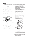
6. Install the blower mounting bracket to the deck
using 1/2-13 x 1-1/2" hex head bolts (p/n 04001-
71), 1/2" spring lockwashers (p/n 04030-06), and
1/2-13 elastic stop nuts (p/n 04021-07). See
Figure 4-3, Page 7. Do not fully tighten the
hardware at this time.
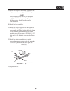
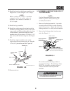
7. Install the catch plate (p/n 423297) to the blower
assembly using 3/8-16 x 1-1/4" carriage bolts
(p/n 04003-11) facing upward. See Figure 4-4,
Page 7. Secure with 3/8" spring lockwashers
(p/n 04030-04) and 3/8-16 elastic stop nuts
(p/n 04021-09). Do not fully tighten the
hardware.
8. Install the blower assembly to the mounting
bracket and secure with the mounting pin. See
Figure 4-4, Page 7.
9. Align the blower assembly with the discharge
opening of the cutter deck. Tighten the
hardware for the mounting bracket. Then
tighten the hardware for the catch plate.
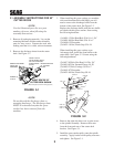
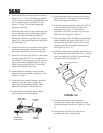
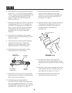
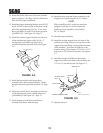
10. Install the belt to the spindle pulley. When
replacing the belt, see figure below.
FRONT SIDE
IDLER PULLEY
BACK SIDE
IDLER PULLEY
BLOWER
PULLEY
SPINDLE
PULLEY
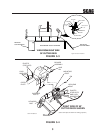
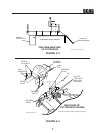
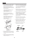
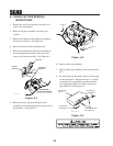
14. Install the catcher support bracket onto the rear
of the machine and secure with 5/16-18 x 1"
carriage bolts (p/n 04003-04) and 5/16-18
serrated flange nuts (p/n 04019-03).
See Figure 4-5.
Catcher Support Bracket
FIGURE 4-5
13. Install the hopper hood assembly onto the
catcher frame assembly and secure with
3/8-16 x 2-1/4" hex head bolts (p/n 04001-46)
and 3/8-16 elastic stop nuts (p/n 04021-09)
See Figure 5-6, Page 13.
11. Install the new belt covers and secure with the
plastic wing nuts. See Page 18 of the Illustrated
Parts List for proper installation.
12. Install the hopper mounting brackets
(p/n 451512) to the outside of the frame on the
rear of the machine using 3/8-16 x 1" hex head
bolts (p/n 04001-19) and 3/8-16 elastic stop nuts
(p/n 04021-09). See Figure 5-6, Page 13.
15. Install the heat shield to the hopper hood
assembly and catcher frame assembly. Secure
using the hardware specified in Figure 5-6, Page
13.
16. Install the catcher frame assembly onto the rear
of the machine and secure with the quick pins
(p/n 04066-03) See Figure 5-6, Page 13.
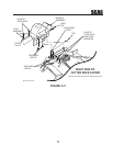
17. Install adapter (p/n 461419) to the blower
assembly and secure with the strap.