


9
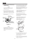
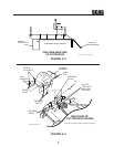
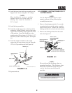
WEIGHT SUPPORT BAR
BAR CLAMP
ELASTIC STOP
NUT
WEIGHT (5x)
LANYARD
PIN
BOLT
2002 GC-STT Install Art 3-5
FIGURE 4-6
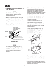
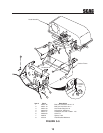
21. Install the weight assemblies to the weight
support bar and secure them to the bar using the
1/2"x 6-1/4" pin and lanyard. See Figure 4-6.
22. Operate and test.
20. Install the weight support bar to the front of the
machine by resting it directly on top of the caster
support arms and sliding it tight against the frame
of the machine. Secure the weight bar to the
machine using (2) bar clamps, (4) 3/8-16 x 1-1/2"
bolts and (4) 3/8-16 elastic stop nuts. See Figure
4-6.
18. Install the hose from the blower assembly to the
hopper hood. Secure using the 8-1/2" clamps.
19. Install the bag assemblies.
-NOTE-
When installing this catcher on machines
equipped with an air cooled engine the
discharge hose should be shortened to
56" in length.
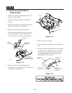
5.1 ASSEMBLY INSTRUCTIONS FOR 72"
CUTTER DECKS
-NOTE-
Use the illustrated parts list as a part
number reference when following the
assembly instructions.
1. Remove all packaging materials. Lay out the
mounting hardware and the catcher assembly
parts for easy access. Prepare the work area
making sure that it is a clean, safe environment.
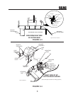
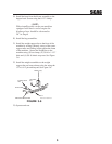
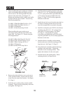
2. Remove the discharge chute from the cutter
deck. See Figure 5-1.
-NOTE-
Do not discard the discharge chute or
mounting hardware. The discharge chute
MUST be reinstalled anytime the grass
catcher has been removed from the
machine.
WARNING
WARNING
DO NOT OPERATE WITHOUT DISCHARGE CHUTE, MULCHING
KIT, OR ENTIRE GRASS CATCHER INSTALLED
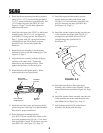
FIGURE 5-1
RIGHT SIDE OF
CUTTER DECK SHOWN
(Note: Some parts not shown for viewing purposes.)
REMOVE DISCHARGE
CHUTE AND
HARDWARE
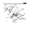
REMOVE EXISTING
RT. SIDE BELT
COVER
INSTALL PULLEY
ON RH SPINDLE SHAFT -
ON TOP OF EXISTING
SPINDLE DRIVE
PULLEY
REMOVE (2)
U-NUTS