


Rover Mowers Limited Chip `N Shred OPERATION
3.8 Screens
Two screens are supplied with the Chip `N Shred, the
standard screen consisting of numerous holes in acurved
plate and a bar screen consisting of widely spaced bars
between two side plates.
The size of the mulch produced by either shredding or
chipping is dependent on the screen fitted to the Chip `N
Shred
The screen to be used depends on the type of material to be
processed. The standard screen suits most types of material
found in the garden. If moist, pulpy or soggy types of material
are to be processed the bar screen should be fitted to avoid
blockages.
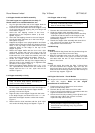
3.9 Screen removal
1. Switch engine off.
2. Remove the spark plug lead from the spark plug or
disconnect the power cord from the power supply.
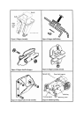
3. When the rotor has come to a stop remove the R-clips
from the screen bars and remove the screen bars, the
screen should then drop out through the discharge chute.
Figure 8.
3.10 Screen fitting
1. Switch the engine off and remove the spark plug lead
from the spark plug or disconnect the power cord from the
power supply.
2. Choose the correct screen for the material to be
processed (refer to section 3.8).
3. Lift and position the screen in the Chip `N Shred by
aligning the holes in the screen and the Chip `N Shred
body. Insert the screen rod closest to the engine first and
secure with the R-clip retainer. Figure 8.
Note: The standard screen can be fitted in the Chip `N
Shred in either direction. The Bar Screen will only fit with
the bars pointing away from the engine.
4. Lift the front of the screen and insert the screen rod
through the Chip `N Shred side plate, retaining with the R-
clip.
CAUTION
Do not tip petrol models over when full of Petrol and Oil.
4. MAINTENANCE
4.1 Oil change Petrol Models
Refer to the manufacturer's instructions.
1. Position the Chip `N Shred on a level surface in a well
ventilated area.
2. Start and run the engine for 5 minutes to warm up the
engine oil.
3. Place a container under the oil drain plug.
4. Using a 7/16" AF open end spanner remove the engine
drain plug and tilt the Chip `N Shred to allow the engine
oil to drain completely.
5. Refit the engine drain plug tightly and clean up any spilt
oil.
6. Fill the engine crankcase with oil. Refer to section 2.6
Engine Lubrication.
4.2 Lubrication Points Petrol Models
Using 10w -30 or S.A.E. 30 oil
1. Clutch lever point.
2. Throttle control.
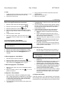
4.3 Drive belt adjustment - Petrol Models
1. Stop the Chip `N Shred and remove the spark plug lead
from the spark plug.
2. Remove the drive belt guard.
3. Move the clutch lever to the engaged position.
4. Loosen the four engine mount bolts.
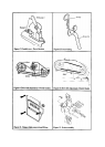
5. Slide the engine away from the Chip `N Shred body to
tighten the drive belt. The drive belt should deflect about
6mm when hand pressure is applied, between the engine
pulley and the rotor shaft pulley. Figure 9.
6. Tighten the engine mount bolts.
7. Replace the drive belt guard aligning the `E' hole with
retaining stud.
8. Move the clutch engagement lever to the disengaged
position and replace the spark plug lead.
CAUTION
Do not over tighten drive belt.
4.4 Drive Belt adjustment - Electric Models
1. Stop the Chip `N Shred and disconnect from the power
supply.
2. Remove the drive belt guard
3. Loosen the four engine mount bolts `A' figure 10.
4. Tension the drive belt to give a 6mm deflection when
hand pressure is applied, by holding the nut `B' with a
9/16" A/F spanner and rotating the bolt `C' clockwise.
5. Tighten the four engine mount bolts.
6. Replace the drive belt guard aligning the `E' hole with
retaining stud.
WARNING
The chipper blade is extremely sharp and caution
must be used when handling or working with it.