


Rover Mowers Limited Chip `N Shred SETTING UP
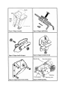
2.2 Hopper handle and baffle assembly
The feed hopper as supplied with the Chip `N
Shred needs to be assembled before use.
1. Lay the right hand side half of the hopper down on
a flat surface with the joint flange pointing up.
2. Position the left hand side half of the hopper on top
of the right hand side aligning the joint flange and
screw holes. Figure 1.
3. Insert the self tapping screws in the front
flanged joint in the sequence shown (1-6) and
tighten. Figure 1.
4. Insert the self tapping screws in the rear flanged
joint in the same sequence as in the front flange
and tighten. Figure 1.
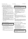
5. Support the hopper in an upright position and fit the
hopper baffle inside the hopper by aligning the four
holes in the top edge of the baffle with the four
matching holes on the ledge in the top of the
hopper. Figure 2.
6. Retain the hopper baffle with the four 3/16" x 5/8"
mush.head screws with the four large 3/16" Flat
washers under their heads and inserted from the
inside with the 3/16" small flat washers and 3/16"
nyloc nuts on the outside of the hopper. Figure 2.
7. Locate the hopper handle and slide it into the
grooves located near the top of the hopper body so
that the holes in the handle are in alignment with
the holes in the hopper. Figure 3.
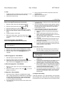
8. Retain the hopper handle with the four 1/4" x 1-1/2"
unc. cuphead bolts inserted from the inside of the
hopper with the four 1/4" unc. nyloc nuts on the
outside. Figure 3.
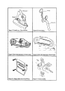
2.3 Hopper assembly to body
WARNING
The hopper assembly must be fitted to the
Chip `N Shred body before attempting to
start or use the Chip `N Shred.
1. Lift the hopper into position on top of the flange on
the Chip `N Shred body with the hopper handle
pointing out over the engine.
2. Align the slots in the hopper flange with the holes
in the body flanges, and insert four 5/16" x 1 " unc
bolts with the hopper washers under their heads.
Figure 4.
3. Retain with four 5/16" washers and four 5/16" nyloc
nuts under the body flange and tighten. Figure 4.
2.4 Chipper tube to body
WARNING
The chipper tube assembly must be fitted to
the Chip `N Shred body before attempting to
start or use the Chip `N Shred.
1. Remove the rotor shaft cover from the bearing.
2. Slide the chipper tube assembly into the
rectangular port on the right hand side of the Chip
`N Shred so that the holes in the flanges on the
chipper tube align with the studs on the Chip `N
Shred body. Figure 5.
3. Retain the chipper tube assembly with three 5/16"
unc. nyloc nuts and three 5/16" flat washers.
4. Replace the rotor shaft cover.
2.5 Mulch bag
Assembly
1. Slide the Mulch bag frame into the pockets along the
top edge of each side of the mulch bag.
2. Slide the spreader tube onto the ends of the bag
frame till the hole in the frame are within the tube
and retain with the two `R' clips inserted into the
holes in the frame.
Fitting
3. Slide the mulch bag under the Chip `N Shred from
the front between the support legs and rest the
mulch bag frame on the rear wheel supports. Lift the
front bar of the mulch bag frame over the front lip on
the front legs support. Figure 6.
2.6 Engine lubrication - Petrol Models
The engine oil level must be checked before attempting
to start the engine. Refer to the engine
manufacturer's instructions.
1. Position the Chip `N Shred on a level surface.
Clean around the dip stick.
2. Remove the dip stick from the oil filler tube.
3. Using a funnel slowly add oil in accordance with the
engine manufacturer's instructions.
4. Check the oil level by screwing in the dip stick and
removing again. When the oil level is correct
replace the dip stick securely.
CAUTION
Avoid premature engine failure by using a
clean funnel and cleaning away any possible
contaminants.