


Rover Mowers Limited Chip `N Shred MAINTENANCE
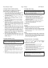
4.5 Chipper blade removal and fitting
Chipper blade removal
1. Stop the Chip `N' Shred
T
M and remove the spark plug
lead from the spark plug, or remove the power cord
from the power supply.
2. Remove the three retaining nyloc nuts and washers
from the chipper tube and lift off.
3. Remove the hopper assembly fasteners and lift the
hopper assembly off the Chip `N' ShredTM body.
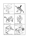
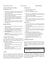
4. Rotate the rotor to expose the chipper blade in the
chipper tube port.
5. Using a 1 /2" AF ring spanner and a Allen key remove
the chipper blade fasteners and remove the chipper
blade. Figure 11.
Chipper blade fitting
1. Clean the surface ofthe rotor plate where the chipper
blade is attached.
2. Using new 5/16" Nyloc nuts fit the chipper blade to the
rotor plate and tighten the nyloc nuts to 19 Nm.
3. Fit the hopper assembly to the Chip 'N' Shred" body.
Refer to section 2.3.
4. Fit the chipper tube to Chip `N' Shred" body. Refer
section 2.4.
5. Move the clutch engagement lever to the disengaged
position and replace the spark plug lead.
4.6 Chipper blade sharpening
To maintain optimum performance from the chipper the
blade should be kept sharp. The chipper blade can be
ground back a total of 3mm before replacement of the
chipper blade is necessary.
1. Remove the chipper blade from the Chip `N' Shred
TM
Refer to section 4.5.
2. Maintain the same angle on the blade cutting edge
when grinding.
3. Remove any feathers that form by lightly honing the
chipper blade on an oil stone.
4. Refit to the Chip `N' Shred
TM
.
Refer to section 4.5.
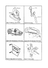
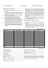
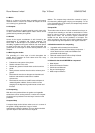
4.7 Flails
The Chip `N' Shred TM is fitted with 12 individual flail
blades. The relative position of the flails on each bar and to
those on other bars is important. If the flail bar is to be
removed for any reason the flails must be reassembled in
the same position as before disassembly. Figure 12.
4.8 Flail removal
1. Remove the hopper assembly.
2. Remove the belt guard.
3. Remove the chipper tube assembly.
4. Rotate the rotor assembly until the flail bar to be
removed is opposite the pilot hole in the left hand side
of the Chip `N' Shred TM body.
5. Remove the flail bar retaining nut and bolt from the
shaft.
6. Using a drift inserted through the pilot hole in the
chipper shredder side plate, drive out the flail bar
through the chipper tube port.
4.9 Flail fitting
1 Determine which flail bar is to be fitted from (Figure
12), and layout next to the Chip `N' ShredTM the flail
blades and spacers.
2 Insert the flail bar through the chipper tube port into the
rotor plate.
3 As the flail bar is being pushed into position, place the
flail blades and spacers on the flail bar as indicated in
figure 12.
4 Replace the flail bar retaining bolt and nut.
5 Fit the chipper tube assembly. Refer section 2.4.
6 Fit the drive belt guard aligning the retainings stud in
the correct hole for Petrol and Electric models.
7 Fit the hopper assembly. Refer section 2.3.
8 Fit the spark plug lead to the spark plug - Petrol
Models.
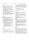
4.10 Routine maintenance
After use, always clean down the outside of the Chip `N'
ShredTM to remove any build-up of material. Visually
inspect all safety labels and replace any that have become
damaged or illegible during operation of the Chip `N'
ShredTM
WARNING
Do not hose down the motor or switch on
electric models
The inside of the Chip `N' ShredTM may be hosed out to
clean away any build up of mulched material. After hosing
out the inside of the Chip `N' ShredTM spray the rotor
assembly, flails and chipper blade with a suitable water
dispersant agent (WD 40).