


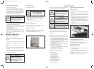


MAINTENANCE
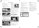
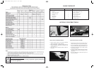
OIL CHANGE
Refer engine manufacturers’ instructions.
1. Place the machine on a level surface. Start and run
the engine for a period to warm the oil.
Fig. 8
2. Fit the drain tube to the drain fitting. Fig. 8
3. Place an oil pan under the end of drain tube.
4. Open the drain fitting about 1 turn and allow the oil
to drain completely.
5. Retighten the drain fitting and refill the sump with
new oil. For correct viscosity and service
classification, refer to the engine manufacturers’
instructions.
SPARK PLUG
The spark plug gap gradually increases during engine
running and should be checked periodically and
whenever the engine malfunctions.
1. Clean around the spark plug area so that dirt will not
enter the engine when the spark plug is removed.
2. Disconnect the spark plug lead and remove the spark
plug.
3. Check the condition of electrodes and ensure there is
no damage to insulator.
4. Carefully clean the spark plug. Do not grit blast.
5. Set the gap between 0.7mm to 0.8mm.
6. Install the spark plug in the engine and tighten.
COOLING SYSTEM
The Ranger has an air cooled 4 stroke engine. It must
be cleared frequently. Remove any build up of grass,
dirt or other debris from the
1. Cylinder
2. Cylinder head cooling fins
3. Cooling air intake screen
4. Carburettor governor levers and linkages.
This will ensure adequate cooling and correct engine
speed.
THROTTLE CONTROL
Proper choke operation is dependant on the
adjustment of remote controls –
1. Loosen the outer cable clamp screw on engine.
2. Set the throttle control to choke position.
3. Adjust the outer cable under clamp plate so that
choke is operated.
4. Tighten the clamp plate screw and check
(a) Choke does not operate in fast position,
(b) Stop switch operates correctly.
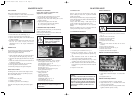
CARBURETTOR ADJUSTMENT
The carburettor has been factory set and should only
require occasional fine tuning.
Refer to Engine Manufacturer’s Owner’s Manual for
details adjustment procedures.
Fig. 11
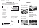
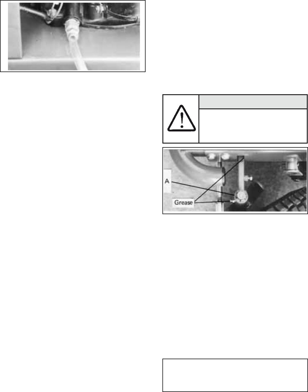
LUBRICATION GENERAL
Using General Purpose Grease – (Every 25 hours)
Grease nipples on front wheel pivots. Fig. 11
Cam plate bearing area. Fig. 26
Front Axle beam guides.
Grease nipples on steering pivot blocks. Fig. 21
Steering gears. Fig. 21
Grease nipples on engagement lever pivot.
Steeing pivot blocks. Fig. 23
Using Clean Engine Oil –
Jockey pivot arms
Throttle control cable.
Drive Chain. Fig. 23
Cutter drive lever pivot.
Clutch/Brake pedal pivot. Fig. 15
Tie rod ball ends. Fig. 11
All connecting rod pivots points.
NOTE:
All ball bearings are sealed and require no
maintenance.
8
MAINTENANCE
CUTTING UNIT
Remove spark plug lead and disengage cutter drive
before working on cutter unit, to prevent accidental
starting of the engine.
Before using the machine always inspect cutting unit to
ensure that the cutting disc, blades and blade fittings are
not worn or damaged.
Always check after striking a solid object. Do not
operate machine when unusual vibration occurs.
Replace worn or damaged blades in sets to preserve
balance.
Remove any build-up of grass or clogging within the
cutting unit, discharge chute or stone guard.
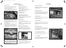
CUTTERHEAD REMOVAL
Fig. 12
1. Disconnect push rods & brake rod. Fig. 12
2. Remove the tensioning spring. A loop has been
provided on the spring to assist in this operation. Fig.
12
3. Slide cutterback towards back of machine and
remove belt from around cutterdeck pulley.
4. Undo large retaining washer bolts (A) Fig. 12 This
will allow front of deck to be lowered to ground.
5. Slide cutterdeck forward. This will allow the rear to
be lowered to the ground and be slid from under the
machine.
6. Replace in reverse order.
NOTE:
To remove cutterdeck belt from machine, the
belt guard has to be moved away from the
drive pulley to allow the belt to be removed
from the V-groove and the cutterhead lifting
rod is to be disengaged from the cutterhead
selection arm assembly to allow belt to be
drawn out.
WHEEL REMOVAL
Fig. 13 Fig. 14
Front –
1. Chock the rear wheels and remove the front axle nut.
Fig. 13
2. Raise the front of the machine.
3. Slide the wheel from the shaft.
4. Replace in reverse order.
5. Re-tighten the axle nut firmly.
Rear –
1. Chock the front wheels and raise the rear of the
machine.
2. Remove the four wheel nuts.
3. Slide the wheel from the hub. Fig. 14
4. Refit the wheel to hub.
5. Replace the wheel nuts and tighten.
BRAKE CALIPER ADJUSTMENT
Fig. 15
1. Loosen locknut ‘A’ Fig. 15
2. Adjust Bolt ‘B’ till brake calliper ‘C’ touches brake
Disc.
3. Re-tighten locknut ‘A’.
BRAKE ARM ADJUSTMENT
1. Check that brake calliper is correctly adjusted.
2. Adjust locknut ‘E’ Fig. 15. Till brake arm ‘D’ Pad
comes into contact with disc.
3. Check operation of brake to ensure park brake can be
applied, and brake operates correctly.
9
WARNING
Always deflate tyre before moving
rim nuts on front wheel only.
CAUTION
Never tamper with the engine
governor setting. Changing of
engine governor speed will
void engine warranty.
2303 Current Artwork 7-2003 18/5/06 2:11 PM Page 10