


7
7. Dirt or abrasives entering the engine via the oil filler
tube due to-
(a) Using a funnel not cleaned of dirt or grit, or,
(b)Topping up with contaminated oil stored in an
unclean container.
8. Lack of oil. It is important to-
(a) Check the oil level regularly (Every 5 hours of
operation)
(b)Maintain a full sump.
Periodically check the machine and the cutting
mechanism. If parts are worn or need replacing do so by
using only Genuine Rover Replacement parts.
Before working on the mower, disconnect the spark plug
lead from the spark plug and place it where it cannot
contact the spark plug.
Check your Rover Ranger frequently for loose nuts,
bolts, belts, etc., and keep these items correctly
tightened and adjusted.
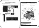
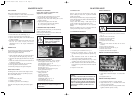
AIR CLEANER
Refer to engine manufacturer’s manual for detailed
instructions.
1. Pull up on air cleaner cover handle and rotate
towards engine.
2. Remove air cleaner cover.
3. Carefully lift air cleaner cartridge and pre-cleaner
from blower housing.
Note: To clean pre-cleaner, wash in soapy water.
Squeeze dry in a clean cloth. DO NOT OIL.
4. Tap the air cleaner on a flat surface to dislodge any
loose debris. If contaminated, replace.
5. Clean the base of the air cleaner cartridge area
carefully to prevent any debris from entering engine.
6. Place the air cleaner pre-cleaner and cartridge into
the blower housing. The cartridge must fit securely
in base.
7. Align the tabs on the cover with the slots in the
blower housing and replace the cover.
8. Hook the handle and close the cover.
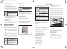
CUTTERHEAD BRAKE
Should be regularly checked for operation.
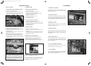
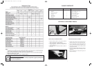
PAD REPLACEMENT
(Refer figure 19)
1. Remove the ‘R’ Clip (A) from
the push rod clevis pin and
remove the clevis pin and push
rod from brake arm assembly.
2. Remove the brake plate pivot
bolt (B), two spacers and
nyloc nut and remove the
brake plate assembly.
3. Drill out the two retaining rivets which hold the Brake pad
assembly to the brake plate and discard the old brake pad and
backing plate. The replacement brake pads are fitted with a
chemically bonded backing plate, locate this backing plate
against the brake plate and retain with two 3/16” rivets. Part No:
A2901195.
4. Replace the brake plate to the cutterhead and adjust the cutterhead
brake.
MAINTENANCE
PARKING BRAKE
Should always be checked for operation after
clutch/brake rods have been adjusted.
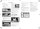
CUTTER DRIVE ADJUSTMENT
1. Move cutter Height Selector Lever to No. 4
Position in Rack.
2. Move cutter Drive Lever to the Engaged position.
3. Adjust Push Rods Fig. 16 to give a spring
compression of 35mm. Fig. 17
Fig. 16
Fig. 20
Fig. 17
Fig. 21
Fig. 18
NOTE:
Check to ensure lever has 30mm of free travel
by working lever.
4. Adjust Locknut ‘A’ to give 7mm clearance to back of
Swivel Block. Fig 17
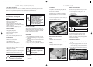
5. Disengage the Cutter Drive Selector Lever.
6. Adjust locknut ‘A’ in Fig. 20 to give Cutter
Engagement Lever a free travel of 30mm, from
bottom of slot in Fig. 18
Fig. 19
CUTTERHEAD BRAKE ADJUSTMENT
1. With the cutterhead disengaged and in low cut
position.
2. Adjust the nyloc nut on the rod as per step 6 for
Cutter Drive Adjustment.
3. Adjust the tension on the spring using the lock nuts
to give length of 58mm. Fig. 20
STEERING GEARS
To adjust the excessive play caused by wear in the
gears.
1. Loosen the bolts securing steering shaft pivot block
(A)
2. Lightly tap the pivot block towards the layshaft pivot
and retighten bolts (A)
3. Check the steering gear engagement.
4. Check that there is no tight spots when turning the
steering wheel from lock to lock.
10
CAUTION
Petroleum solvents, such as
kerosene, are not to be used to
clean cartridge. They may cause
deterioration of the cartridge.
DO NOT OIL CARTRIDGE.
DO NOT USE PRESSURIZED
AIR TO CLEAN OR DRY
CARTRIDGE.
2303 Current Artwork 7-2003 18/5/06 2:11 PM Page 9