


MAINTENANCE
Fig. 28
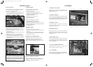
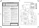
Fig. 26
12
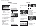
TO FIT NEW BELT
4. Ensure that the peg on rack assembly (A) engages in
the front slot of cam plate assembly. (B) Fig. 26
5. Fit new drive belt around pulleys.
6. Draw the spring plate back into position and secure.
Check that the spring finger (C) engages in the first
couple of teeth on the rack assembly. Fig. 26
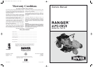
Fig. 27
If the spring finger engagement in the rack assembly is
not at the start of the rack assembly, proceed as follows:-
7. Release the spring plate as per step (2)
8. Loosen the four locknuts (A) on the engine hold
down bolts. Fig. 27
9. Loosen locknuts (B) on engine pulley guard and
slide to the rear. Fig. 27
10.Adjust nyloc nut (C) on motor adjustment plate to
move the engine to the rear and repeat step (6).
11.Re-tighten engine mounting bolts and re-position
belt guard with 2-3mm clearance between belt guard
and engine pulley.
NOTE:
After a period of time the drive belt will stretch
past the limit of the auto-tensioner. The auto-
tensioner can be reset to allow for this stretching
by following the above instructions- steps (7) to
(11). Re-grease the bearing area under cam plate
when fitting new belt. Fig. 26
STEERING RODS
Should not normally require resetting.
1. Loosen the rod lock nut (A). Fig. 11
2. Release the fixing bolt.
3. Turn the tie rod end to adjust for length.
Clockwise to shorten, anti-clockwise to lengthen.
4. Replace the fixing bolt and tighten.
5. Tighten the rod lock nut.
6. Make sure the rod is free to pivot.
CUTTER HEAD TILT
This will not normally require resetting.
1. Loosen the U-Bracket nuts (B) Fig. 12
2. Adjust the nuts up or down to set tilt.
3. Model 160 (760mm cut) requires the back of the
blade circle tilted 15mm above the front of the blade
circle in low cut position.
4. Re-tighten all nuts.
STEERING STOPS
These will not normally require resetting.
1. Check if the steering segment gear rotates in both
directions.
2. Loosen the locknut on the front beam and adjust the
bolt till number of turns in both directions is equal.
3. Re-tighten the Locknut.
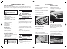
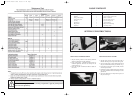
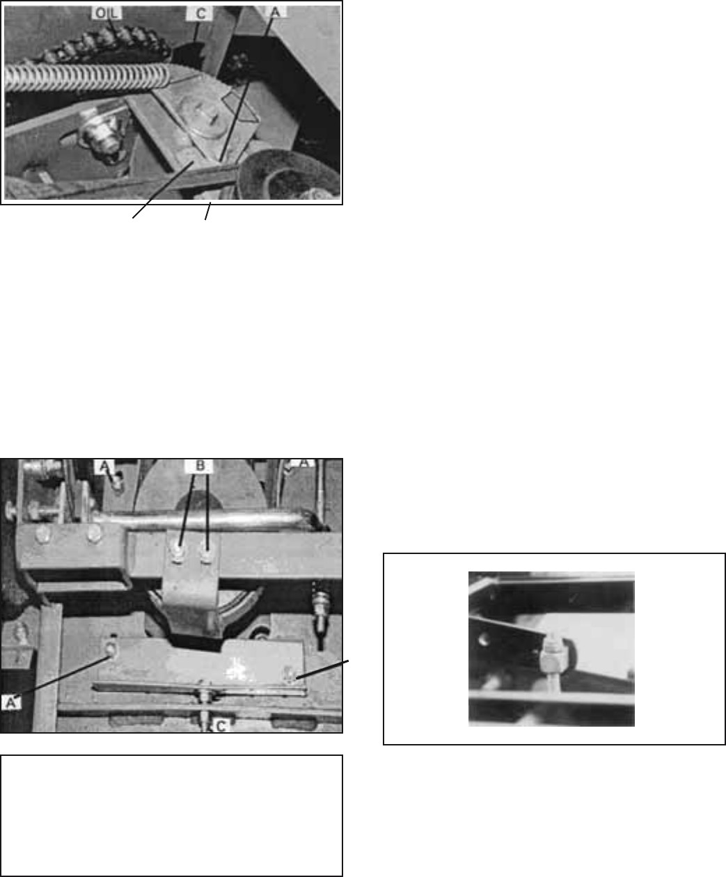
HEIGHT OF CUT ADJUSTMENT
To adjust the height of cut rotate the nyloc nut (A)
situated under the centre of machine on the rear
cutterhead support assembly. Adjust the nyloc nut to
obtain low cut at front of blade circle of 15mm. Fig. 28
SAFETY INTERLOCK SYSTEM
The safety interlock system has been designed for your
protection and should not be tampered with. It gives
the Ranger the following characteristics.
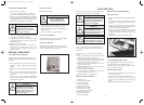
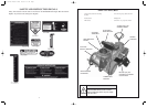
CONTROLS
1. THROTTLE CONTROL
Mounted on the control panel and connected to the
engine carburettor controls. Has the symbols for Slow,
Fast and Choke. Fig. 6
2. IGNITION SWITCH
This switch is part of the battery ignition system and has
three positions marked for Off, On and Start. The switch
is key operated and automatically returns to the On
position from the Start position when released. Fig. 6
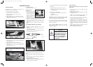
3. BRAKE/ CLUTCH
Foot operated pedal on the left side of machine.
Depressing the pedal neutralises the drive belt and
engages the Brake Disc. Fig. 7
4. PARKING BRAKE
Hand operated knob left hand side. Depressing the
brake/clutch foot pedal enables this knob to be engaged
and disengaged. Brake is locked on with knob in up
position. Fig. 7
5. DRIVE SELECTION
Foot operated right hand side. Depress with toe pressure
gives forward motion, depress with heel gives reverse
motion. Automatically returns to neutral position when
foot is removed. Fig. 7
6. CUTTING HEIGHT ADJUSTER
Located on right side of seat. (Fig. 7) with low cut at
bottom and high cut at the top setting. Fig.7
7. CUTTER DRIVE
Lever located on left hand side of seat mounting box.
Down position disengages blade drive and applies blade
brake, up position engages blades. Fig. 7
5
Fig. 6
Fig. 7
B
GREASE
1
2
6
7
4
3
5
A
2303 Current Artwork 7-2003 18/5/06 2:11 PM Page 7