


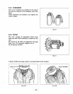
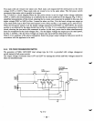
Two main coils are wound over stator core. Each main coil outputs half the rated power at the lower
voltage (llOV or 120V). These main coils are wound to be
in
the same phase. The full power switch
reconnects these main coils in parallel or in series.
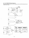
Fig.
5-9
shows a circuit diagram-When the full power switch
is
set for single lower voltage indication
(llOV or 120V), the switch position is as indicated by the lower solid line in the diagram. Fig. 5-10 is a
simplified representation of this circuit, showing the two main coils connected in para1lel.h this case, the
higher voltage (220V or 240V) at Rec.
3
cannot be taken out. Rec. 2 for the lower voltage
can
output up
to the rated power (up to
30A
if the rated current is over
30A),
and Rec. 1 can output up to a total of 15A.
When the full power switch is set for double voltage indication (llOV/220V or 120V/240V), the switch
position is as indicated by the upper dotted line in Fig.
5-9.
Fig. 5-11 is
a
simplified representation
of
this
circuit, showing the two main coils connected in series. In this case, power can be taken simultaneously
from the receptacles for the both voltages. Rec.
3
for the higher voltage can output
up
to the rated power,
but Rec. 1 and Rec. 2 for the lower voltage can output only up to half the rated power each.
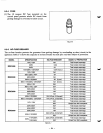
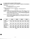
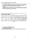
Table 5-4 is
a
summary of the above explanation. Select the proper output voltage by full power switch in
accordance with the appliance to be used.
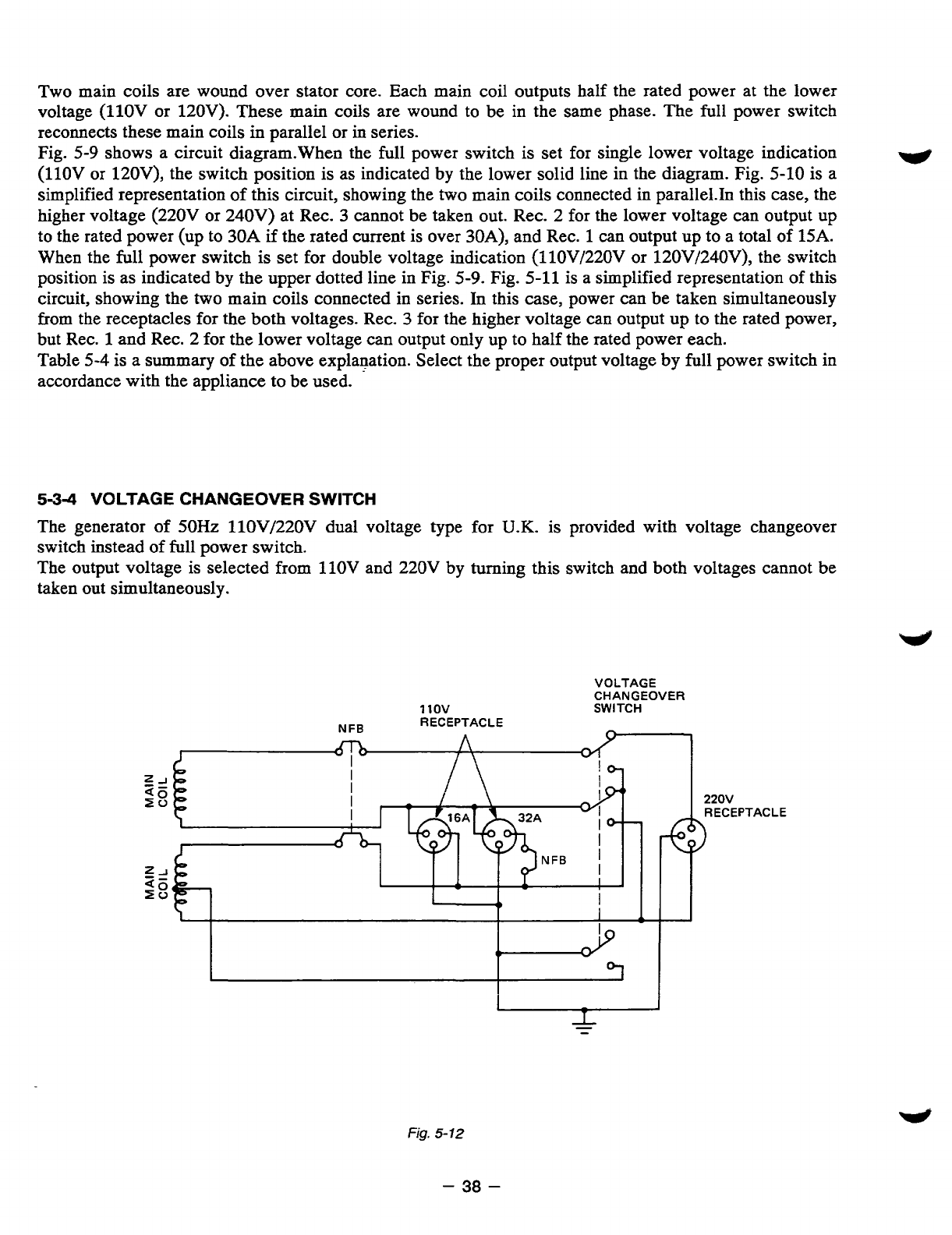
5-34
VOLTAGE
CHANGEOVER
SWITCH
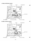
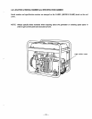
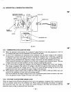
The generator of 50Hz llOV/220V dual voltage type for
U.K.
is provided with voltage changeover
switch instead of full power switch.
The output voltage is selected from llOV and 220V by turning this switch and both voltages cannot be
taken out simultaneously.
VOLTAGE
CHANGEOVER
11ov
SWITCH
RECEPTACLE
NFB
J
Fig.
5-
12
-
38
-