


7.
MAGNETO
7-1
MAGNETO
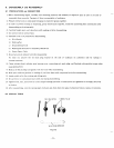
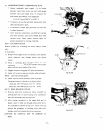
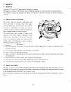
In Models EY33-2 and EY44-2, ignition spark is furnished by a magneto.
The magneto is composed
of
the flywheel, ignition coil, lighting (charging) coil, breaker assembly (including condenser).
The flywheel is mounted
on
crankshaft, while ignition coil, lighting coil, and breaker assembly are directly assembled
to
crankcase.
7-2
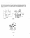
BREAKER POINT ADJUSTMENT
The breaker points are mounted inside flywheel and
directly assembled to crankcase. Check breaker points
whenever ignition spark becomes weak. If there
is
evidence
of
pitting or pyramidding, the breaker points must be
corrected and then, it becomes necessary to readjust the
gap to its proper clearance (0.35mm,
0.014
inch).
The normal breaker point opening is 0.35mm at full
separation. Since spark timing is regulated by point
opening, use a timing light to obtain an accurate spark
advance.
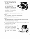
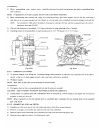
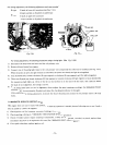
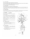
To
adjust the breaker point opening, remove
starting pulley and flywheel from engine and observe
following procedures. (see Fig.
7-2)
Remove point cover from crankcase.
Turn the crankshaft until breaker arm comes
in
contact with the highest point
of
breaker cam (muximum point
opening
of
0.35mm).
Loosen contact support plate lock screw just enough to move bracket.
Insert a 0.35mm feeler gauge between points.
Apply
a
screwdriver to adjusting tab, and move contact support plate just enough
to
obtain specified gap, while opening
and closing points.
Clamp the setscrew
of
contact support plate, and check the point gap again.
Pull a strip
of
8
to lOmm wide white paper through closed points
to
remove dust and oil.
After adjustment, assemble the point cover, flywheel, and starting pulley to engine.
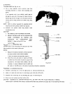
7-3
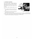
TIMING ADJUSTMENT
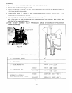
The spark is timed to occur 23" before the piston reaches
TDC
on the compression stroke. This spark advance
of
23' is
controlled by the breaker point opening and this advance is obtained when the breaker point opening is adjusted according
to the BREAKER
POINT ADJUSTMENT
to
0.35mm
(0.014
inch).
However, the advance timing
is
more accurately adjusted through the following procedures using
a
timing light as shown in
Fig.
7-3-2.
-1
8-