


6)
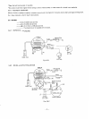
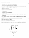
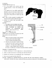
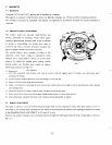
ADJUSTING
TAPPET
CLEARANCE
(Fig.
6-3-5)
*
Rotate crankshaft until tappet is in its lowest
position, hold valve down and insert feeler gauge
between valve and tappet stem. The clearance for
both intake and exhaust, with engine cold.
0.13-0.17mm (0.0051”to 0.0067“)
*
If clearance is less than specified, slightly grind valve
stem and measure it again.
*
If
clearance
is
larger than specified, sink valve seat
to adjust clearance.
*
After clearance adjustment, assemble valve springs
and valve retainers, and secure them
in
place with
retainer locks. Check tappet clearance again for
proper adjustment by turning crankshaft.
6-3-9
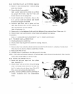
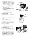
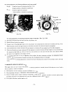
CYLINDER BLOCK
Detach cylinder by loosening one 8mm and five lOmm
nuts.
In reassembly;
Remove from upper surface
of
cylinder, carbon deposit
which otherwise may damage piston when piston
moves.
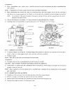
lnsert a doubling plate between piston skirt and
crankcase, and set piston to the cylinder center
so
that
piston will not move easily. (Fig. 6-3-6).
Stagger the piston ring gaps
90°
apart around piston.
Apply
oil
to piston ring and cylinder walls sufficiently.
NOTE:
Use
new cylinder
gasket.
5)
Check if piston moves smoothly after reassembly.
Clamping torque of cylinder
is
as shown below.
8mm nut 170-190 kgcm
(12.3-1
3.7
ft-lbs.)
lOmm nut 350-400 kg-cm (25.3-29 ft-lbs.)
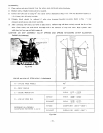
6-3-70.
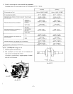
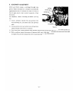
MAIN BEARING COVER
I)
Unscrew 6mm bolt located
just
below crankshaft on
driving shaft side of main bearing cover and
8
pieces
bolts for mounting main bearing cover.
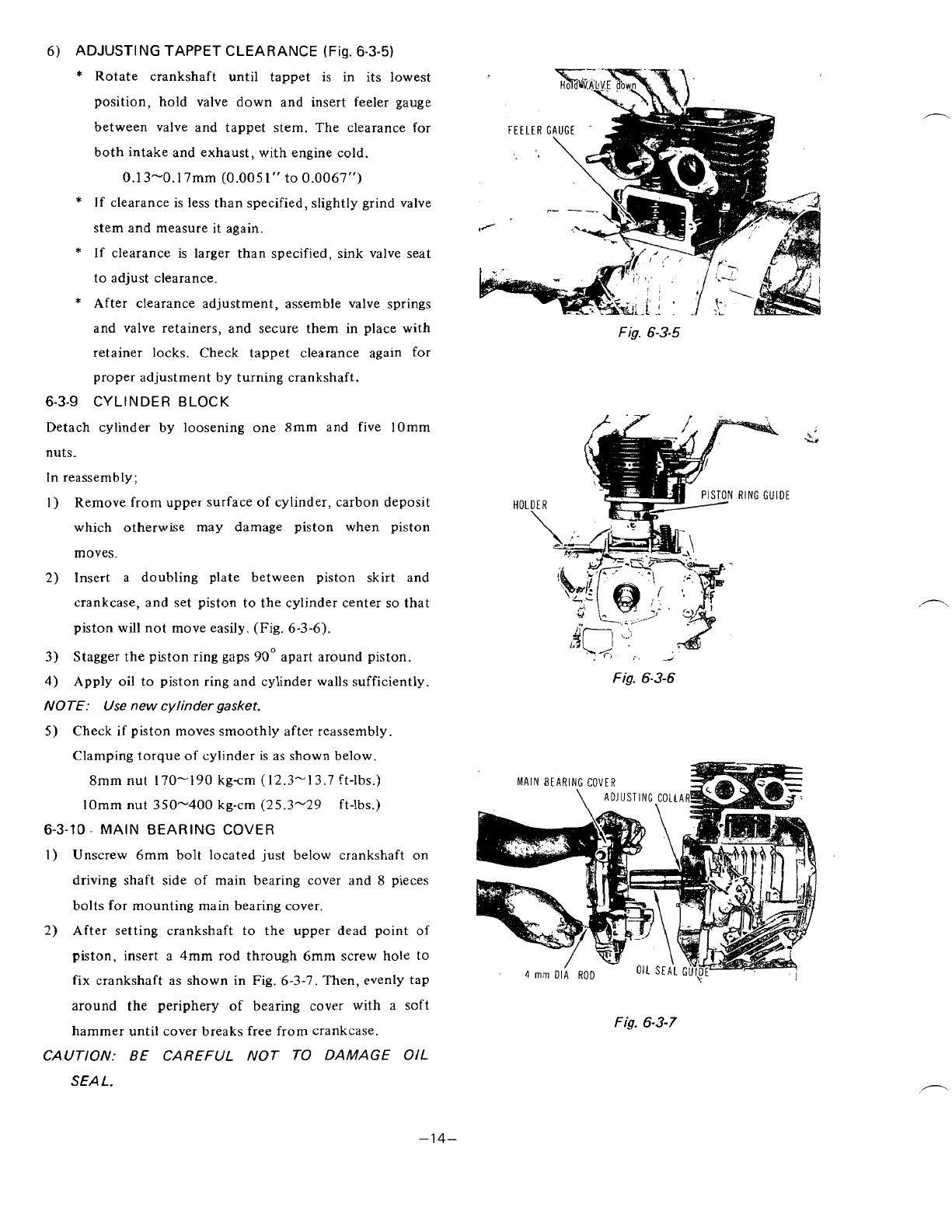
2) After setting crankshaft to the upper dead point
of
piston, insert a
4mm
rod through 6mm screw
hole
to
fix
crankshaft as shown in Fig. 6-3-7. Then, evenly tap
around the periphery of bearing cover with a soft
hammer until cover breaks free from crankcase.
CAUTION:
BE
CAREFUL NOT
TO
DAMAGE
OIL
SEA
1.
Fig.
6-3-5
RING
GUIDE
HOLDER
\
.
1;
:~
d
Fig.
6-3-6
MAIN
BEARING
COVER
Fig.
6-3-7
”1
4-