


4-2
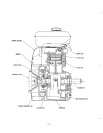
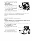
CRANKCASE
The crankcase is made
of
aluminum die-cast and separable on driving shaft side with main bearing cover assembled.
Provided on blower side are two ball bearings, each supporting the crankshaft and camshaft.
4-3
MAIN BEARING COVER
The aluminum die-cast main bearing cover on the driving shaft side allows easy access
to
the engine interior
for
inspection
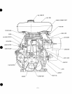
simply by removing it. The’fange and boss permit direct coupling of operating machines such as generators, pumps, etc.
The oil inlets which
also serve as oil gauges can be mounted on driving shaft side of Models
EY33-2B
and
EY44-2B.
The force-fit balancer shaft and balancer holder mounting boss assure easy mounting of the balancer mechanism.
44
CRANKSHAFT
The crankshaft is machined from carbon steel forging with an induction hardened crank pin. The breaker cam
is
provided on
blower side, while crankshaft gear and balancer gear are force-fit on driving side.
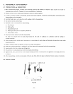
4-5
CONNECTING
ROD
and PISTON
The connecting rod
is
machined from aluminum alloy forging, and forged alloy itself serves as bearing metal at both ends.
(Model
EY44-2 employs aluminum metal on the large end.)
An
oil
scraper is provided on the large end for the purpose of splashing lubricating oil. The piston is machined fron
aluminum alloy casting and provided with grooves for two compression rings, one oil rings, and one skirt ring.
The
EY44-2
piston has
an
offset structure at the piston pin center
so
as
to reduce striking sound of piston.
4-6
CAMSHAFT
The carbon steel forging camshaft incorporates integral intake and exhaust cams plus a force-fit cam gear.
The
B-typ
camshaft
also
serves
as
driving shaft and it
is
driven at half the crankshaft speed.
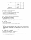
4-7
CYLINDER and CYLINDER HEAD
The cylinder is made
of
special cast iron and provided with many fins for assuring excellent cooling effects. The cylinda
head is made
of
aluminum alloy casting. The Ricardo type combusion chamber with a sufficient area assures hil
combusion efficiency. The spark plug
is
tilted
to
facilitate fuel tank mounting.
4-8
VALVE ARRANGEMENT
The exhaust valve
is
positioned in the upstream of the colling
air
so
that it is intensively cooled down for improv
durability
of
engine.
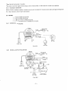
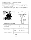
4-9
BALANCER
An unbalanced inertia force produced due to crankshaft and piston connecting rod in the vertical and lateral direction:
balanced by balancer which rotates at
a
ratio of
1:
1
in the direction opposite to crankshaft,
so
that vibrations due
unbalanced inertia force are reduced.
-6-