


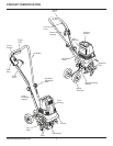
www.remingtonpowertools.com
8
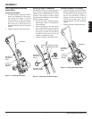
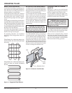
ADJUSTING WHEEL ASSEMBLY
Adjusting the Wheel Assembly for
Transport
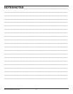
1. Remove retaining clip and clevis pin
from wheel assembly mounting bracket
(see Figure 4).
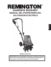
2. Rotate the wheel assembly down so that
the hole in the wheel assembly lines up
with the center hole in the mounting
bracket as shown in Figure 5.
3. Insert the clevis pin through the hole as
shown in Figure 5, and insert the retain-
ing clip in the clevis pin. The wheels are
now mounted in the transport position.
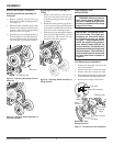
Adjusting the Wheel Assembly for
Tilling
1. Remove the retaining clip from the
clevis pin and remove the clevis pin
from the mounting bracket and wheel
assembly.
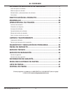
2. Rotate the wheel assembly up and for-
ward as shown in Figure 6 until the hole
in the wheel assembly lines up with the
upper hole in the mounting bracket.
3. Insert the clevis pin through the aligned
holes and insert the retaining clip into
the clevis pin. The wheels are now
mounted in the tilling position.
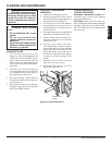
TINE REMOVAL AND
INSTALLATION
Tine Removal and Installation
1. Remove the retaining clips from the
end of the tine shaft.
2. Remove outer tine set from tine shaft.
3. Remove inner tine set from tine shaft.
4. Reinstall the retaining clips onto tine shaft
to prevent them from being misplaced.
5. Reverse above steps to install tines.
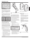
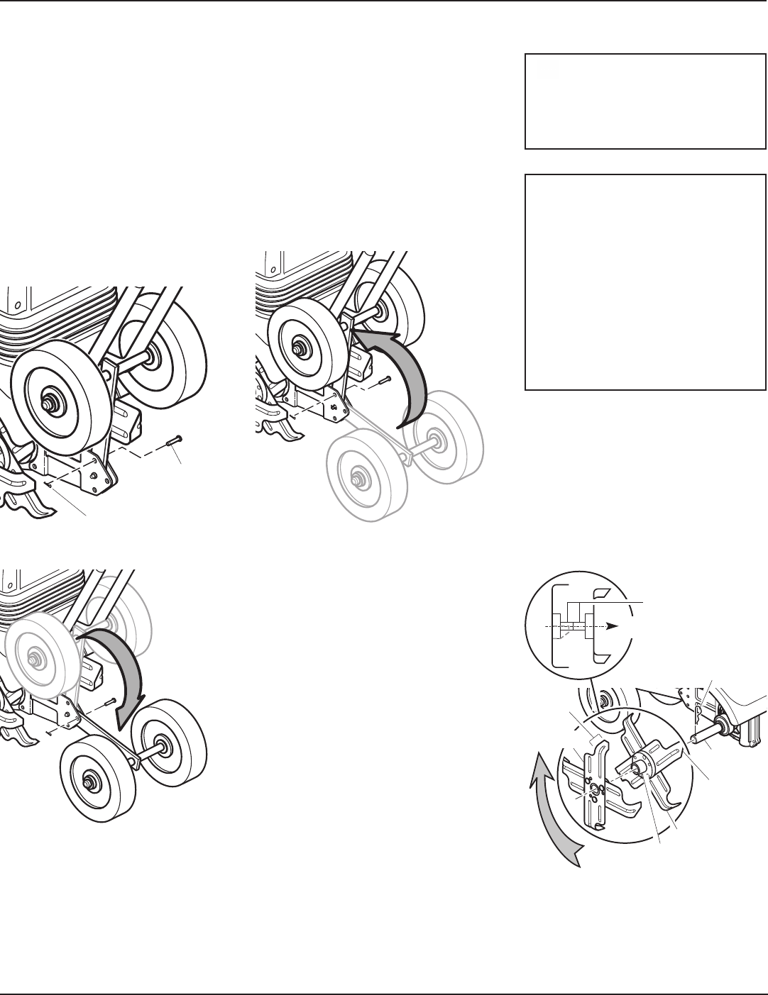
IMPORTANT: The tiller has 4 differ-
ent sets of tines. For proper per-
formance, the tines must always
be installed correctly as shown
in Figure 7. When assembled cor-
rectly, the angled cutting edge of
tines should rotate towards the
front of the tiller. The blades of all
the tines should be pointing toward
the transmission. The tine hubs of
the inner and outer tine sets should
be facing each other as shown in
Figure 8.
WARNING: Always unplug the
tiller before placing hands near
the tines. Always wear gloves to
protect your hands from the sharp
edges of the tines.
Tine Shaft
Inner Tine Set
Retaining Clip
Figure 7 - Tine Removal and Installation
Clevis Pin
Figure 4 - Removing Retaining Clip and
Clevis Pin
Figure 5 - Adjusting Wheel Assembly to
Transport Position
Figure 6 - Adjusting Wheel Assembly to
Tilling Position
Retaining Clip
Rotation of Tines
During Operation
Cutting
Edge
Tine Hub
Tine
Blade
Outer
Tine Set
Tine Hubs
Toward Transmission
ASSEMBLY