


4
Motor Type ..................................................................................................................... Electric, Corded
Motor Voltage ...................................................................................................................120 VAC, 60HZ
Motor Amperage .......................................................................................................................5.5 Amps
Motor Speed (no load) .............................................................................................................7,000 rpm
Trimming Line Diameter .............................................................................................0.065 in. (1.65 mm)
Cutting Path Diameter .....................................................................................................14 in. (35.6 cm)
Weight ....................................................................................................................................7 lb (3.2 kg)
CLEANING AND STORAGE
Cleaning Instructions
• Use a fi rm-bristled, non-wire, brush to remove debris from the unit.
• Wipe the unit down with a damp cloth. Do not douse the unit with water. Do not use solvents or
strong detergents.
Storage Instructions
• Follow the Cleaning Instructions listed above.
• Store the unit indoors in a dry, high and/or locked location, out of the reach of children and other
unauthorized persons.
WARNING: Do not let brake fl uids, gasoline, petroleum-based products, penetrating
oils, etc., come in contact with plastic parts. These chemicals may damage, weaken
and destroy plastic, which may result in serious personal injury.
TROUBLESHOOTING
CAUSE SOLUTION
THE MOTOR WILL NOT RUN
The cord is not securely connected to the unit
or power sour
ce
Make sure each plug is securely connected
The GFCI in the outlet has tripped (if used) Reset the GFCI
THE CUTTING HEAD WILL NOT ADVANCE LINE
The cutting head is bound with grass
Clean the cutting head
The cutting head is out of line Refi ll the cutting head with new line
The spool is bound up Replace the spool
The cutting head is dirty Clean the spool and hub
The line is welded
Remove the welded section and rewind the line
The line twisted when it was refi lled Rewind the line
THE CUTTING HEAD ADVANCES LINE UNCONTROLLABLY
The cutting head is broken Refer to the Service section
NOTE: For maintenance beyond the minor adjustments listed above, or for replacement parts, please
call the Customer Support Department at 1-866-206-2707 (U.S.) or 1-877-696-5533 (Canada).
SPECIFICATIONS
* All specifi cations are based on the latest product information available at the time of printing. We
reserve the right to make changes at any time without notice.
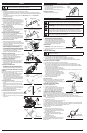
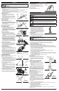
LINE INSTALLATION
ADDING NEW LINE
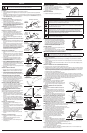
1. Press and hold the two cap release latches (Fig. 15).
2. Pull the cap away from the hub.
3. Remove the spool.
4. Use a clean cloth to clean the spool and inner
surface of the hub.
5. Cut two 10.5 feet lengths of replacement line.
NOTE: Always use original equipment manufacturer
0.065 in. (1.65 mm) replacement line. Other line
may make the motor overheat or fail.
NOTE: Always use the correct line length. The line
may not release properly if it is too long.
6. Insert one line into each of the two slots on the spool
(Fig. 16).
7. Wind the line onto the spool by turning the spool
clockwise (Fig. 17). The line should wrap snugly
around the spool. Do not twist or cross the line.
Wind the line until there are approximately 4 inches
remaining.
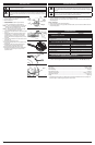
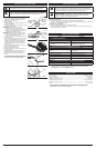
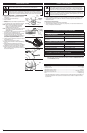
8. Lock the ends of the lines in the two notches on the
spool (Fig. 18).
9. Put the spool back into the hub.
10. Insert a line through each of the two eyelets on the
hub (Fig. 19).
11. Straighten the lines by removing them from the
notches. Make sure the lines feed smoothly.
12. Securely place the cap back onto the hub.
13. Manually extend the lines to the line cutting blade.
See Adjusting the Trimming Line Length in the
Operation section.
WARNING: Never use metal-reinforced line, wire, chain or rope. These can break off
and become dangerous projectiles.
WARNING: Before inspecting, cleaning or servicing the unit, stop the motor, wait
for all moving parts to stop, disconnect the unit from the power source and allow it to
cool. Failure to follow these instructions can result in serious personal injury or property
damage.
Fig. 16
Fig. 17
Fig. 15
Cap
Release
Latch
Cap
Hub
Spool
Cap
Release
Latch
Fig. 18
Notches
Fig. 19
Eyelet
WARNING: Before inspecting, cleaning or servicing the unit, stop the motor, wait
for all moving parts to stop, disconnect the unit from the power source and allow it to
cool. Failure to follow these instructions can result in serious personal injury or property
damage.