


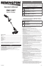
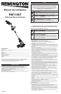


3
This unit requires assembly.
UNPACKING
• Carefully remove the product and any accessories from the box.
• Inspect the product carefully to make sure no breakage or damage occurred during shipping.
• Do not discard the packing material until you have carefully inspected and satisfactorily operated
the product.
• If any parts are damaged or missing, please call 1-866-206-2707 (U.S.) or 1-877-696-5533
(Canada) for assistance.
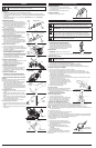
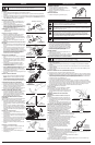
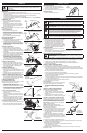
ASSEMBLING THE SHAFT
1. Remove and discard the rubber grommet (Fig. 1).
2. Align the arrows on the upper and lower shafts (Fig. 2).
3. While pushing the shaft length adjustment button up
toward the rear handle, slide the upper shaft over
the lower shaft until they lock together (Fig. 2).
NOTE: Once assembled, the upper and lower shafts
will not separate again.
Adjusting the Shaft Length
1. Grip the shaft housing fi rmly.
2. While pushing the shaft length adjustment button up
toward the rear handle, move the upper shaft up or
down to the desired length.
3. Release the shaft length adjustment button.
INSTALLING THE CUTTING HEAD SHIELD
1. Align the arrow on the cutting head shield with the
arrow on the motor housing (Fig. 3).
2. Twist the cutting head shield counterclockwise, in
the LOCK direction (Fig. 3), until it snaps into place.
Make sure the cutting head shield is assembled as
shown in the Know Your Unit section.
INSTALLING THE D-HANDLE
1. Remove the knob and bolt from the D-handle.
2. Push the D-handle down onto the upper shaft (Fig. 4).
Some force is required. The hex bolt hole in the handle
should be on the left side.
3. Insert the bolt into the hex hole in the handle and
push it through (Fig. 4). Screw the knob onto the
bolt. Do not tighten the knob completely.
4. While holding the unit in the operating position (Fig.
11), move the D-handle to the location that provides
the best grip. Place it a minimum of 6 inches (15.24
cm) from the end of the rear handle.
5. Tighten the knob until the D-handle is secure.
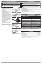
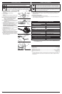
ADJUSTING THE SHAFT ANGLE
1. Squeeze the shaft angle adjustment buttons on both
sides of the motor housing (Fig. 5).
2. Rotate the shaft to one of the four settings, as
needed to reach under decks, bushes, etc.
CONVERTING TO EDGER MODE
1. Grip the shaft housing fi rmly.
2. Press the edger conversion button and rotate the
rear handle until it locks in place (Fig. 6 and 7).
3. Make sure the wire guard is fl ipped up against the
motor housing (Fig. 8).
ADJUSTING THE WIRE GUARD
1. Rotate the wire guard up or down to the desired
position (Fig. 8). The wire guard helps keep the
trimmer line away from fences, curbs, fl owers, etc.
CONNECTING AND DISCONNECTING THE POWER
SOURCE
Follow these instructions in order to avoid injury and to
reduce the risk of electric shock or fi re:
• Verify that the switch trigger is disengaged before
connecting or disconnecting the power source.
Refer to the Starting and Stopping section.
• Verify that the unit is disconnected from the power
source and the switch trigger is disengaged before
inspecting, adjusting or performing maintenance on
any part of the unit.
Connecting the Power Source
1. Connect the power cord plug to the extension cord
(Fig. 9).
2. Make a narrow loop with the extension cord and
push the loop through the opening for the cord hook
(Fig. 9).
3. Move the loop onto the cord hook and pull the cord
gently to secure the loop over the hook. This helps
prevent accidental disconnection.
4. Connect the extension cord plug to the outlet.
Disconnecting the Power Source
1. Disconnect the extension cord plug from the outlet.
2. Remove the loop in the extension cord from the cord
hook.
3. Disconnect the power cord plug from the extension
cord (Fig. 9).
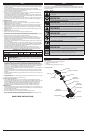
OPERATION
ASSEMBLY STARTING AND STOPPING
WARNING: Make sure the unit is disconnected from the power source before
assembling, disassembling or adjusting any components.
Fig. 1
Lower
Shaft
Rubber Grommet
Upper
Shaft
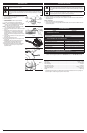
STARTING THE MOTOR
1. Connect the unit to the power source. Refer to
Connecting and Disconnecting the Power Source in
the Assembly section.
2. Squeeze and hold the switch trigger (Fig. 10).
STOPPING THE MOTOR
1. Release the switch trigger (Fig. 10).
Fig. 10
Switch
Trigger
PROPER GRIP
• Always maintain a proper grip on the handles
whenever the motor is running. Grip the unit
fi rmly with both hands. Keep the left hand on the
D-handle and the right hand on the rear handle. The
fi ngers should encircle the handles and the thumbs
should wrap under the handles. The left arm should
be straight and the right arm slightly bent.
PROPER STANCE
• Balance body weight securely, with both feet on
solid ground.
• Hold the unit at waist level. The cutting head should easily contact the grass without the need to
bend over (Fig. 11).
WORK AREA PRECAUTIONS
• Keep everyone – helpers, bystanders, children and animals – at least 50 feet (15 m) away from the
work area. If anyone enters the work area, stop the unit!
• Only operate the unit when visibility and light are adequate to see clearly.
• Remove stones, nails, glass and wire from the area before operating the unit.
• Only operate the unit during reasonable hours. Comply with times listed in local ordinances.
OPERATING THE UNIT AS A TRIMMER
1. Start the motor. Refer to the Starting and Stopping section.
2. Slowly move the cutting head into and out of the cutting area at the desired height.
• Move either in a forward-backward or side-to-side motion. When cutting from side-to-side,
cut from right to left whenever possible. This improves the unit’s cutting effi ciency and directs
clippings away from the operator.
• Keep the cutting head parallel to the ground.
• Cutting shorter lengths produces the best results.
• Cut grass over 8 inches (200 mm) by working from top to bottom in small increments to avoid
premature line wear or motor drag.
• Do not force the cutting head. Allow the tip of
the line to do the cutting, especially along walls.
Cutting with more than the tip will reduce cutting
effi ciency and may overload the motor.
• Only trim when grass or weeds are dry.
3. Dispose of debris appropriately.
Decorative Trimming
Decorative trimming is accomplished by removing all
vegetation around trees, posts, fences and more.
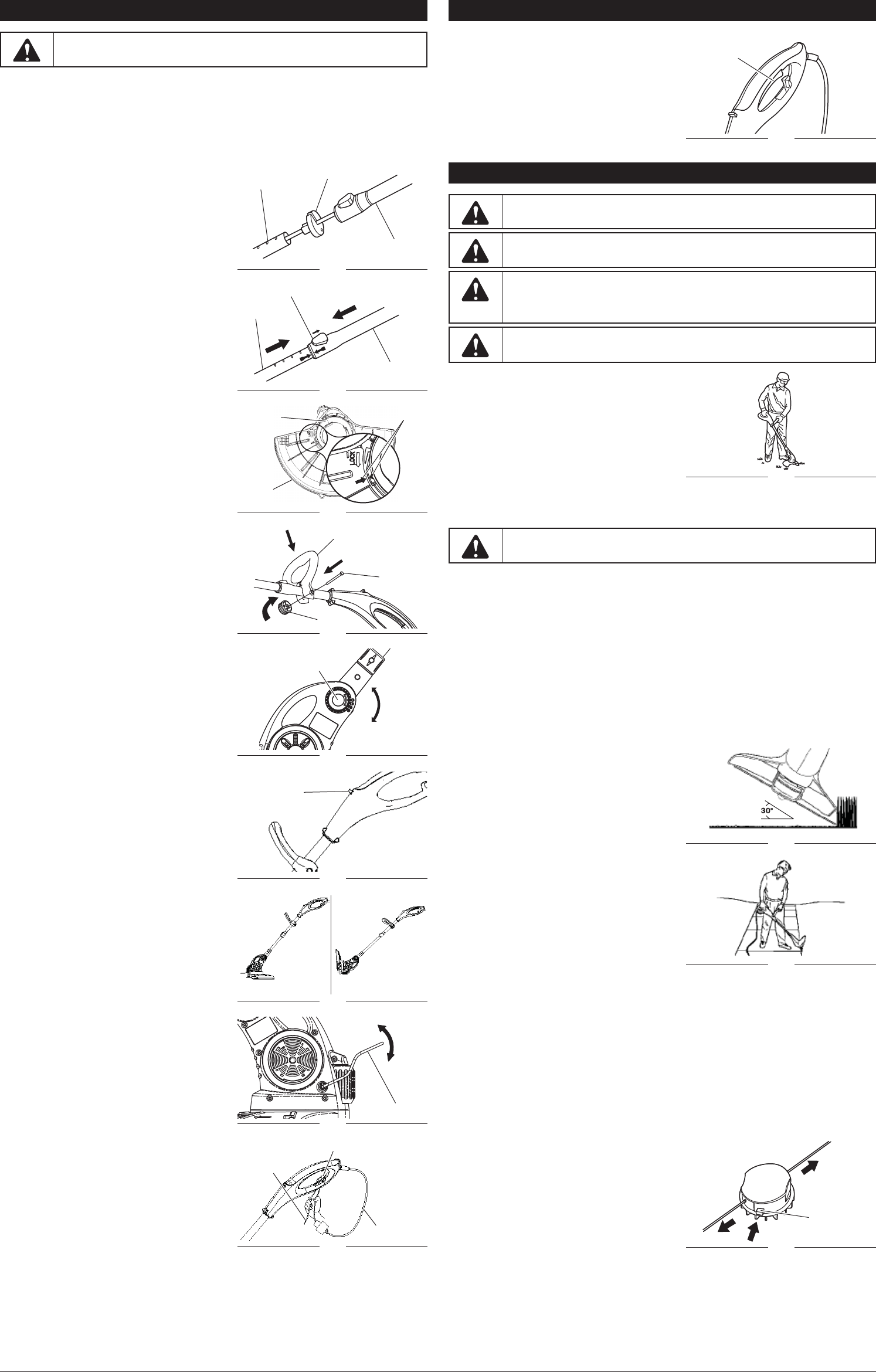
• Rotate the whole unit so that the cutting head is at a
30° angle to the ground (Fig. 12).
OPERATING THE UNIT AS AN EDGER
Tips for Best Edging Results
• Convert the unit to edger mode.
• Hold the unit with the motor to the operator’s left
side so that debris is thrown to the rear (Fig. 13).
• Place the edge guide wheel on the sidewalk,
driveway, etc. and the trimmer line in the grass.
ADJUSTING THE TRIMMING LINE LENGTH
The trimming line wears down and becomes shorter
with use. This unit is equipped with an EZ Line Advance cutting head. The cutting head will
automatically dispense more line whenever the unit is stopped and restarted.
NOTE: DO NOT bump the cutting head; this will damage the unit and void the warranty.
NOTE: Always keep the trimming line fully extended. Line release becomes more diffi cult when the
cutting line gets shorter.
If the line becomes too short:
1. Stop the motor. See the Starting and Stopping section.
2. Wait two seconds and then restart the motor.
3. Repeat this process until the line length reaches the line cutting blade on the cutting head shield.
The line cutting blade will cut the line to the proper length if any excess line is released. Remove the
protective material from the line cutting blade before using the unit.
The trimming line can also be extended manually:
1. Stop the motor
2. Disconnect the unit from the power source.
3. Press and release the manual line release button
while gently pulling both lines until they reach the
line cutting blade (Fig. 14).
The life of the cutting line is dependent upon:
• Following the trimming techniques previously
explained
• What vegetation is cut
• Where the vegetation is cut.
For example, the line will wear faster when trimming
against a foundation wall as opposed to trimming
around a tree.
WARNING: Do not allow familiarity with this unit to promote carelessness.
Remember that a careless fraction of a second is enough to infl ict serious injury.
WARNING: If any parts are damaged or missing, do not operate the unit until the
parts are replaced. Failure to heed this warning could result in serious personal injury.
WARNING: Always wear appropriate eye and ear protection when operating this
unit. Wear safety goggles, or safety glasses with side shields, that are marked as
meeting ANSI Z87.1-1989 standards. Failure to do so could result in serious eye injury
caused by thrown objects. If the operation is dusty, wear a face mask or dust mask.
WARNING: Wear non-slip gloves for maximum grip and protection. Refer to the
Safety section for appropriate safety equipment.
WARNING: Do not expose the unit to rain. Do not use the unit in damp or wet
locations or conditions.
Fig. 11
Fig. 2
Upper
Shaft
Lower
Shaft
Shaft Length Adjustment Button
Fig. 4
Bolt
Knob
D-Handle
Fig. 3
Arrows
Cutting
Head
Shield
Motor
Housing
Fig. 5
Shaft Angle
Adjustment Button
Fig. 6
Edger
Conversion
Button
Fig. 8
Wire Guard
Fig. 7
Trimmer
Mode
Edger
Mode
Fig. 9
Cord Hook
Power Cord
Extension
Cord
Fig. 12
Fig. 14
Manual Line
Release Button
Fig. 13