


C) Electrical
1. The electrical installation must be in
accordance with current BS. 7671
(I.E.E. regulations).
2. The unit should be connected into a switched
3 amp double pole fused spur, with a
minimum contact gap of 3mm in each pole.
The switch must be fitted outside the
bathroom.
Alternatively, a double pole ceiling switch, with
a pull cord and a minimum contact gap of
3mm in each pole could be used inside the
bathroom.
For additional safety, it is recommended that a
residual current device be used with either of
the above switches.
3. The earth continuity conductor of the
electrical installation MUST BE effectively
connected electrically to all exposed parts of
the appliances and services in the room in
which the water heater is to be installed in
conformity with the current BS. 7671 (I.E.E.
wiring regulations).
WARNING : THIS APPLIANCE MUST BE
EARTHED.
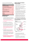
4. We recommend using 1.0mm
2
Twin and Earth
cable for this application. Connect the mains
cable in to the terminal block, ensuring that all
power is switched off before connecting to the
mains supply.
Recommended order : -
a) Strip back wire approximately 6.0mm.
b) Ensure wires are secure in the correct
terminal block holes.
c) Ensure that the mains cable is securely
clamped in the cable clamp provided
on the backplate.
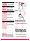
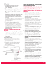
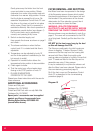
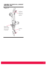
5. Schematic wiring diagram.
FINAL INSTALLATION PROCEDURE
AND COMMISSIONING
WARNING : DO NOT switch on the electricity
supply until the following procedure has
been completed. Failure to do so could
cause the pump to run dry and invalidate the
guarantee.
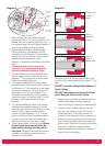
1. Fit the shower hose to the outlet of the
shower unit. Do not connect the handset at
this stage. Ensure that the water isolating
valves are fully open and that the hose is
directed to waste.
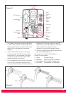
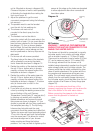
2. The shower unit is factory set in the
commissioning mode. A commissioning link is
connected to the p.c.b. (see diagram 2),
which opens the solenoid without switching
on the motor. This allows water to flow
through the pump, thus ensuring that all air is
removed.
The cover is not required to be fitted at this
stage but be aware of live parts when the
electricity is temporarily switched on.
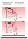
3. Switch on electrical supply. After a few
moments water should drip from the hose.
It may be necessary to hang the hose
from the shower unit whilst priming
especially if the head of the water is
minimal. This will speed up the priming
process.
When water drips through the hose at a
constant rate. Stop flow of water by switching
off the electrical supply.
Ensure electricity is switched off. Remove
p.c.b. commissioning link. Replace with the
connector attached to the front cover
start/stop/flow control switch.
Store commissioning link in a safe place
for future use.
4. Ensure side section is in place (see diagram
2). Refit cover using 3 fixing screws. Attach
handset to shower hose.
5. A temperature limiter is provided so that the
maximum working temperature can be set.
The limiter is factory set but can be adjusted
depending on incoming water conditions.
The limiter is visible when Temperature Control
Knob 'B' is removed (see diagram 14).
Diagram 15
9
Start/Stop
switch
Potentiometer
PCB
Motor
Solenoid
Terminal
Block
Double pole
isolating switch
220–240V Mains supply consumer fuse box
NL