


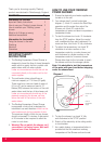
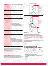
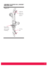
Gently prise away the limiter from the front
cover and rotate to new position. Rotate
clockwise for a cooler stop position and anti-
clockwise for a warmer stop position. Ensure
that the limiter is pressed firmly home. Re-
assemble Temperature Control Knob 'B' over
the drive on the mixer unit and fix into place
with a screw. Check that it's movement is
restricted sufficiently. Also check operation of
temperature override button (see diagram 1).
Re-fit control knob cap by positioning
correctly and pressing firmly home.
6. Switch on electrical supply and
then operate the shower as shown on page 2
and check : -
a) The shower switches on when the flow
control knob 'A' is rotated and that flow is
adjustable.
b) Temperature can be adjusted by knob 'B'
and the limiter position is satisfactory (ie. Not
hot enough to scald).
c) Operation of override button allows the
temperature limiter position to be overridden.
d) Check again for leaks.
e) That the motor turns off and water stops
flowing in the STOP position of knob 'A'
7. PLEASE DEMONSTRATE
OPERATION TO THE USER.
Please leave these instructions with the user for
future reference.
ADDITIONAL ACCESSORIES
Curtain and Rail pack
Catalogue No. 83-792802
Curtain and Rail Pack with non-slip Bath Mat
Catalogue No. 83-792801
Spare parts / accessories can be supplied
against any Visa or Access cards from
Redring Sales Hotline 0870 9000 420
(normal office hours).
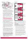
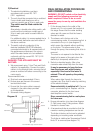
FILTER REMOVAL AND REFITTING.
Inlet filters have been incorporated in the design
of the Expression power shower which protect
the internal mechanisms of the shower unit and
the handset. If the performance of the shower
deteriorates (ie. Flow reduction occurs) then it
may be necessary to clean the filters.
WARNING : ISOLATE FROM MAINS
ELECTRICITY AND WATER SUPPLY BEFORE
REMOVING THE COVER TO MAKE CHECKS.
Remove shower cover as described in note 6 on
page 6. The cover will be connected to the PCB
via a flying lead. Carefully pull the lead from the
PCB.
DO NOT let the front cover hang by the lead
as this will damage the PCB.
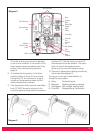
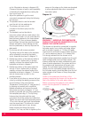
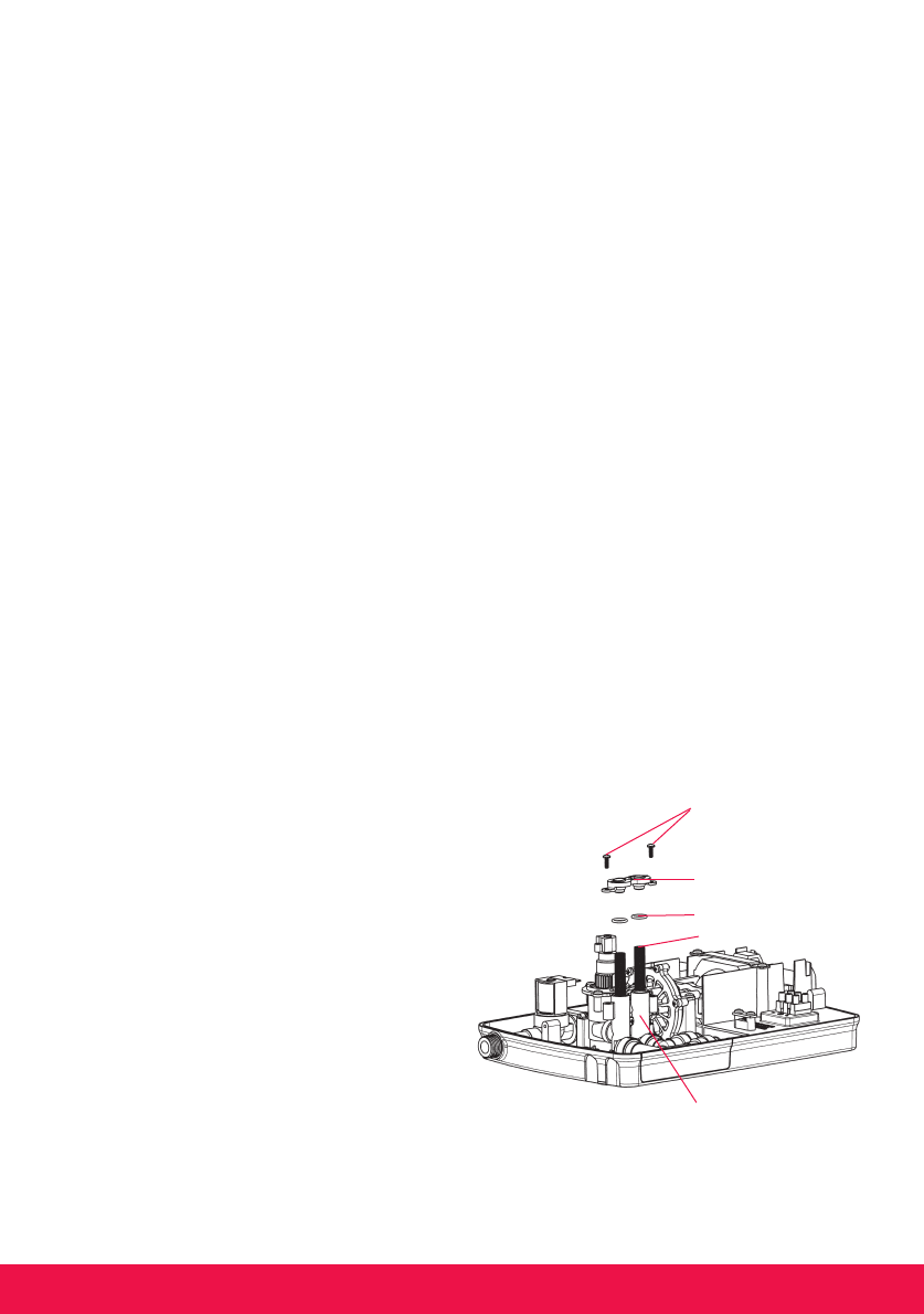
The filters are positioned in the inlet housing as
shown in diagram 13 below. Remove 2 fixing
screws and the filter cap from the housing and
remove both filters. Wash thoroughly under
running water and replace in housing. Ensure that
both 'O' seals are fitted to the filter cap and re-
assemble cap using 2 fixing screws.
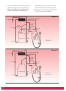
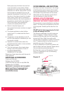
It may be necessary to re-prime the shower unit
after the filters have been cleaned. Please refer to
the commissioning procedure (page 9).
Re-fit the front cover and Temperature Control
Knob 'B' as described in the commissioning
procedure (page 9).
10
Fixing Screws
Filter Cap
'O' Seals
Filters
Inlet Housing
Diagram 13