


unit ie. Mounted as shown in diagrams 5/6.
Choose a flat piece of wall to avoid possibility
of distorting the backplate thus making the
front cover a poor fit.
3. Adjust the positions to get the most
convenient arrangement taking the following
into account : -
a) The possible need to use the handset
over the sink for hair washing etc.
b) The shower unit must not be
mounted in the direct spray from the
handset.
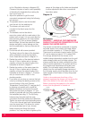
c) The handset must not be able to
come into contact with the used water in the
cubicle, bath or basin. If it can, even after the
hose has been retained by the hose retainer
(see diagram 12), then a vacuum breaker
must be fitted. It should be noted that these
devices are liable to minor leakage so they
must be positioned so that any drips are not
detrimental
3. Fix the riser rail with screws provided.
The fixing holes at the base of the brackets
will be revealed by removing the plastic
fronts. Assemble as shown in diagram 12.
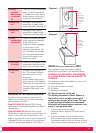
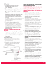
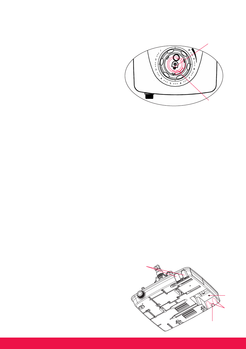
4. Decide the position of the electrical cable to
the unit. If top or bottom entry is chosen,
carefully cut away the relevant walls of the
backplate as shown in diagram 7.
5. Decide the position of the water pipes into
the unit. If top or bottom entry is chosen,
carefully cut away the relevant walls of the
backplate as shown in diagram 7. If bottom
entry is chosen refer to note 8 in the
plumbing section.
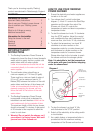
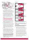
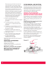
6. If you have not yet done so, remove the front
cover by undoing the retaining screws at the
top and bottom of the unit. Remove
Temperature Control Knob 'B' cap (see dia.1)
by levering out carefully with a small flat
bladed screwdriver and remove the small
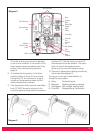
fixing screw as shown in diagram 14. Your
shower is provided with four fixing positions in
the backplate (see diag. 2). The top fixing
holes are key-hole slots and the most
convenient should be marked and drilled first.
Tighten top screw with head protruding about
10 mm from the wall and hook the backplate
over the screw head. This allows for correct
and accurate alignment of your shower
before marking and fixing the bottom
positions. You may not wish to tighten up the
screws at this stage as the holes are elongated
to allow adjustment after other connections
have taken place.
B) Plumbing
WARNING : - UNDER NO CIRCUMSTANCES
SHOULD THIS UNIT BE CONNECTED TO THE
MAINS COLD WATER SUPPLY.
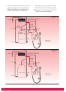
The shower unit should be connected to a gravity
fed water supply from a static cold water cistern
with a minimum capacity of 114 litres (25 galls).
There must be a minimum head of water of 8.0cm
(3'') and a maximum head of 10.0 metres (33ft).
It is strongly advised that the shower unit is
installed using independent supplies from the cold
water storage cistern and hot water cylinder. The
shower would then be totally unaffected by other
draw off points elsewhere in the system and thus
the pressure and temperature will remain more
stable. The cold water supply should be taken
directly from the cold water storage cistern and
the hot water supply should be taken from the hot
water cylinder via an Essex or Surrey flange (see
diagram10).
Under no circumstances should any of the
pipework supplying the shower unit rise above the
level of the bottom of the cold water cistern.
Before connecting the pipework to the shower
ensure that the pipework is flushed out.
Rear
entry
recess
Optional
knock-
outs for
water
pipe
entry
from top
Top entry
cable knock
out (optional)
Optional
knock-outs for
water pipe entry
from bottom
Diagram 7
6
Diagram 14
Small fixing
screw
Temperature limiter
(visible when knob
'B' removed)