


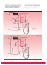

1. Surrey Flange (Top entry cylinder flange)
Fitting Instructions. The hot connection to the
Shower unit can be taken directly from the
hot cylinder using a Surrey Flange. Diagram 10
shows how this flange should be fitted.
2. Essex Flange (Side entry cylinder flange)
Fitting Instructions. Alternatively, the hot
connection to the Shower unit can be taken
directly from the hot cylinder using an Essex
cylinder flange and extension pipe.
Diagram 10 explains how the flange should be
fitted.
Connecting direct to the side of the
cylinder is not recommended where a
top entry immersion heater is fitted.
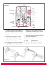
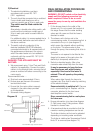
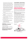
3. The hot connection can also be taken from
the hot supply to other outlets as shown in
diagram 11. The connection must be made
below the ventilation pipe tee.
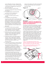
4. In all cases a dedicated cold water supply
should be taken from the cold water cistern to
the shower unit. The connection in the cistern
should be made below the level of the cold
water feed to the hot water cylinder. The
connection should also be on the opposite
side of the cistern to the float valve. This will
prevent air being sucked into the pump
chamber.
5. It is recommended that water council listed
isolating valves are fitted between the cold
water storage cistern and the shower unit and
between the hot water cylinder and the
shower unit (see diagrams 10/11). This will
allow the shower unit to be serviced without
turning off the cold water at the water stop
valve and draining the cold water cistern.
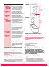
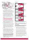
6. 15mm copper pipes should be used. Ensure
all burrs have been removed from the
pipes before inserting into the push fit
inlet ports. Diagram 9 illustrates the correct
procedure for inserting and removing the
pipes from the inlet ports.
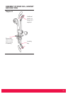
Short fixing
screw
Long fixing
screw
Side
section
'O' ring
seals
Combined
inlet elbow
Diagram 8
Diagram 9
A
B
C
Simply push
in tube to
attach
Tube is
secured in
position
Push in
collet to
release tube
Take care to line up the inlet pipe correctly with
the inlet port to avoid straining the internal 'O' ring
seal.
DO NOT use solder fittings within 300mm of
plastic fittings.
DO NOT insert fingers into the push-fit inlet
ports. Doing so could result in injury.
7. Keep pipe runs as short as possible and use
swept bends rather that right angled or
restrictive fittings to optimise the performance.
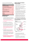
8. If bottom entry has been chosen, the inlet
port must be rotated through 180
0
into the
required position. To do this unscrew the
combined inlet elbow (as shown in diagram 8)
and remove the side section from the shower
unit. Remove combined elbow and rotate for
bottom entry. Slide back into position ensuring
that the 'O' seals are correctly in place.
Replace side section and tighten 2 screws in
elbow to lock into position.
7