


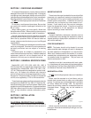
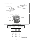
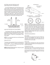

GAS PRESSURE REGULATOR
The gas pressure regulator is preset and sealed at 4 in.
WC for natural gas, and 11 in. WC for propane gas.
Between the gas valve and the burners is a 1/8" pipe plug.
The pressure at this point, taken with a manometer,
should be about 3.7 in. WC natural gas and 10.5 in. WC
propane gas. If an adjustment is needed, remove seal
and turn adjustment screw clockwise , to
increase pressure or counterclocwise , to
decrease pressure.
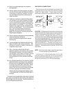
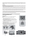
GAS PRESSURE MANOMETER
TEST UPSTREAM
MANUAL
SHUT-OFF
VALVE
GAS PRESSURE TEST
AT GAS VALVE
GAS PRESSURE TEST
AT HEATER
Fig. #8149.0
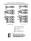
PIPE SIZING FOR GAS CONNECTIONS
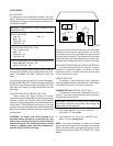
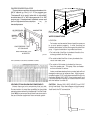
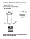
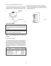
VENTING OF DIAPHRAGM GAS COMPONENTS
Heaters have gas train components that have dia-
phragms in their construction are supplied with a bleed
line connection that must be connected to the outside
atmosphere as required by the National Fuel Gas Code.
Under NO circumstances shall bleed lines terminate in
the gas utilization equipment flue or exhaust system.
7
Bleed
Line Connection
Fig. # 8185.2
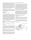
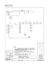
WATER CONNECTIONS
LOCATION
The heater requires water flow and positive pressure
to fire and operate properly. It must therefore be
installed downstream of the discharge side of the filter
pump. A typical installation is plumbed as follows:
1.The inlet side of the filter is plumbed directly to the
discharge side of the filter pump;
2.The outlet side of the filter is then plumbed to the
inlet of the heater; and
3.The outlet of the heater is plumbed to the return
line to the pool or spa. The pump, filter and heater
are thus plumbed in series.
Heater must be located so that any water leaks will not
damage the structure of adjacent area. High tempera-
ture plastic pipe (CPVC) may be connected directly into
the heater Models 926-1223, if local codes permit and
if controls operate the pump for at least fifteen minutes
after the heater is turned off.
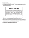
CAUTION (Models 926-1223): NEVER install PVC
directly into heater. Four feet of copper or high tempera-
ture pipe and two elbows are required between the
heater and the PVC connections.
Fig. # 8129.0