


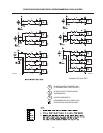

(a) Seal any unused openings in the common
venting system.
(b) Visually inspect the venting system for proper
size and horizontal pitch and determine there is
no blockage or restriction, leakage, corrosion
and other deficiencies which could cause an
unsafe condition.
(c) Insofar as is practical, close all building doors
and windows and all doors between the space
in which the appliances remaining connected
to the common venting system are located and
other spaces of the building. Turn on clothes
dryers and any appliance not connected to the
common venting system. Turn on any exhaust
fans, such as range hoods and bathroom
exhausts, so they will operate at maximum
speed. Do not operate a summer exhaust fan.
Close fireplace dampers.
(d) Place in operation the appliance being inspected.
Follow the lighting instructions.
Adjust thermostat so appliance will operate
continuously.
(e) Test for spillage at the drafthood relief opening
after 5 minutes of main burner operation. Use
the flame of a match or candle, or smoke from
a cigarette, cigar or pipe.
(f) After it has been determined that each
appliance remaining connected to the common
venting system properly vents when tested as
outlined above, return doors, windows, exhaust
fans, fireplace dampers and any other gas
burning appliance to their previous conditions
of use.
(g) Any improper operation of the common venting
system should be corrected so the installation
conforms with the latest edition of the National
Fuel Gas Code, ANSI Z223.1/NFPA 54. When
re-sizing any portion of the common venting
system, the common venting system should be
re-sized to approach the minimum size as
determined using the appropriate tables in Part
11 of the National Fuel Gas Code, ANSI Z223.1/
NFPA 54.
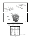
For special venting applications that require reduced
vent sizes and through the wall venting, the optional D
Series Power Vent can be used. Consult the factory or
your local Raypak representative.
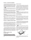
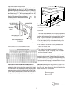
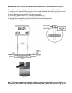
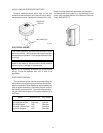
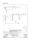
GAS SUPPLY CONNECTIONS
Gas piping must have a sediment trap ahead of the
heater gas controls, and a manual shut-off valve located
outside the heater jacket. All gas piping should be
tested after installation in accordance with local codes.
MANUAL SHUT HEATER GAS VALVE
OFF VALVE JACKET
GAS INLET
UNION
SEDIMENT
TRAP
FIG. #8090.0
CAUTION: The heater and its manual shut-off valve must
be disconnected from the gas supply during any pressure
testing of that system at test pressures in excess of 1/
2 psig (3.45 KPA). Dissipate test pressure in the gas
supply line before reconnecting the heater and its manual
shut-off valve to gas supply line. FAILURE TO FOLLOW
THIS PROCEDURE MAY DAMAGE THE GAS VALVE.
OVER PRESSURIZED GAS VALVES ARE NOT COV-
ERED BY WARRANTY. The heater and its gas connec-
tions shall be leak tested before placing the appliance in
operation. Use soapy water for leak test. DO NOT use
open flame.
NOTE: Do not use teflon tape on gas line pipe thread.
A flexible sealant is recommended.
A minimum of 7 in. WC and a maximum of 10.5 in. WC
upstream pressure under load, and no load conditions
must be provided for natural gas or a minimum of 11 in.
WC and a maximum of 13 in. WC for propane gas.
6