


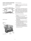
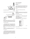

CONTROL WELL REPLACEMENT
Remove top, sensing bulb and clip. Collapse well
tube at the open end and with a chisel, push through into
the header, and remove the well through header. Insert
a new well and roll into place. If a roller is not available,
solder the well in place with silver solder.
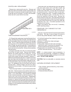
IMMERSION WELL
25
Fig. #8126.0
TUBE REPLACEMENT PROCEDURE
On Raypak tube replacement may be affected without
rolling, as a temporary means of repair, provided there are
two or more tubes rolled into act as stays on left and right
sides. The "O" rings should provide a seal up to 125 PSI
working pressure. Use a 3/8" heavy duty reversible drill
motor or larger, to power the tube roller. If a reversible drill
is not available, after rolling the tube in, remove the drill
motor and wrench out the roller. A tube roller is available
from the factory.
Shut gas and power off to the unit, close the system
off and drain the pool heater. Remove draft diverter.
Remove the access panels and jacket top. Lift the
canopy and flue collector off (on models 926-1826,
remove the canopy hold-down brackets). Remove "V"
baffles over tube(s) to be replaced. If no pipe unions have
been provided, use the header as a union, remove the
flange nuts off the inlet-outlet header, break gas connec-
tion and slide boiler away from piping, allowing room to
work. Pull wedge slips out of control wells and remove
sensing bulbs. Remove flange nuts from the return
header and remove header. Lift heat exchanger straight
up and out.
Heat exchanger header o-rings must be replaced with
new ones. The tube may be cut out with a hack-saw or
hammer and chisel adjacent to both tube sheets, leaving
stubs in the tube sheets. Then proceed to collapse
stubs in the tube sheets with a chisel or screwdriver. Use
caution not to cut into the tube sheet. Replacement
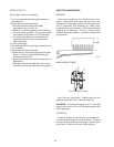
tubes will have the fins stripped off longer on one end. The
long end is inserted into the opening of the tube sheet
first; then the short end is fitted through the opposite tube
sheet. If the tube ends become dented or bent, straighten
at least four (4) inches back from the tube end by means
of a tapered punch.
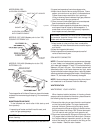
Insert tube roller into tube opening up to stop against
tube, then push center rod in until roller is tight. Be
careful to keep replacement tube squared up 1/8"
outside each tube sheet. A loose tube will sometimes
pull toward the roller. Attach drill motor to tube roller,
holding it straight and level. Proceed to expand tube
until the tool begins to grab. At this point, 1/2" to 1"
should be exposed on the tool shank. Reverse drill
motor or wrench out by hand. Care should be exercised
to avoid applying excessive torque during rolling opera-
tion and to avoid thinning out any part of the tube wall
excessively over .015". Use same procedure at the
opposite end of the tube.
Apply line pressure test, and re-roll, if necessary,
before replacing canopy.
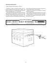
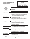
PROCEDURE FOR CLEANING FLUE GAS
PASSAGEWAYS
Soot can clog areas behind fins and cause eventual
tube failure. Any sign of soot at base of burners or
around outer jacket indicates a need for cleaning.
1.Lift off draft hood and flue collector by removing
bolts and screws.
2.Remove "V" baffles from heat exchanger.
3.Remove burner tray.
4.Take garden hose and wash heat exchanger,
making sure soot is removed from between fins.
(Avoid excessive water against refractory).
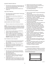
5.Reassemble; when boiler is fired, some steam
will form from wet refractory. This is normal.
NOTE: In extreme cases it may be necessary to
remove the heat exchanger completely for cleaning.
The simplest method is steam cleaning at a local car
wash. DO NOT WIRE BRUSH!
CAUTION: Soot is combustible, so exercise extreme
care.
UNITHERM GOVERNOR REPLACEMENT
1.Shut off water, gas and electricity, close valves,
relieve pressure.
2.Drain heat exchanger.
3. Remove Unitherm Governor.