


10
Raypak recommends the installation of an air bleed vent at a suitable location (usually the highest point) to remove
air from the piping system. These units should be available at your local wholesale supplier. Raypak does not provide
this item.
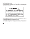
CAUTION:
Power to the heater should be interlocked with the main system pump to make sure the heater does not
fire without the main system pump in operation.
Improper flow control can damage the heater. Uncontrolled flow (too high) or restricted flow (too low) can
seriously affect heater operation. Follow these instructions to make sure your heater is properly installed.
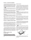
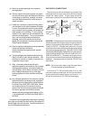
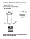
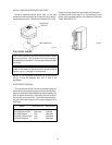
Models 1287 through 4001 are equipped with an external pump and bypass arrangement that blends outlet water with
the inlet to increase the inlet water temperature, thereby reducing the likelihood of condensation forming on the heat
exchanger. The pump also serves to circulate water through the heater from the main system piping.
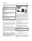
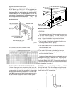
To complete the installation of the pool heater, the pool thermostat needs to be installed in the main return water line.
This will ensure that the heater will be energized at the right time. If the main water line is too far away from the heater
and the capillary bulb will not reach it, locate the pool thermostat adjacent to the main line and run wires back to the
heater. Follow the instructions listed below to install the pool stat.
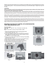
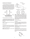
MOUNTING THE POOLSTAT CONTROL WITH FRONT-MOUNTED
LOOP USING MOUNTING SLOTS
For heater models:
1287, 1336, 1414, 1468, 1571, 1631, 1758, 1826, 2100, 2500, 3001,
3500, 4001.
Note: For more detail on piping, see figures 9268 and 9269.
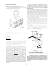
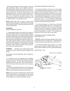
1. Remove the poolstat control cover by removing the two cover
screws at the top. See Figs. 1 & 2.
2. Lace metal strapping or clamps, (NOT PROVIDED) through the ¾”
slots on the cover and fasten securely to pipe as shown in Figs. 3
& 4. NOTE: Do not over-tighten clamps.
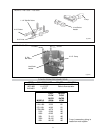
3. Remove either the left or right “knock-out” for wiring on the poolstat
control as shown in Fig. 5.
4. Attach appropriate conduit and connectors to the poolstat control.
5. Attach wires to the poolstat wire terminals. See Fig.6.
6. Install poolstat control to the cover and fasten cover screws.
7. Poolstat should be mounted level as shown in Fig. 7.
Fig. 1: Poolstat Control
Fig. 2: Control Cover
Fig. 3: Hose Clamp Slots
Fig. 4
Fig. 5 Fig. 6 Fig. 7