


FLAME ROLL-OUT SAFETY SWITCH
The heater is equipped with a thermal cutoff device to
prevent flame roll-out in the event the heat exchanger
becomes blocked. This is a "Single-use" type fusible link
or thermal fuse, that must be replaced when disabled by
an over temperature condition, caused by excessive
restriction in the heat exchanger flue passage.
HIGH LIMITS
The heater is equipped with two automatic high
limits. Both are located in the inlet/outlet header. Both
are set to open at 135°F.
NOTE: An erratic high limit is often characteristic of
internal heat exchanger problem, i.e. scale buildup,
defective bypass. Refer to troubleshooting sections.
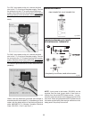
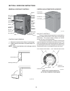
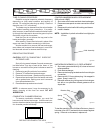
HIGH LIMIT REMOVAL
29
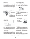
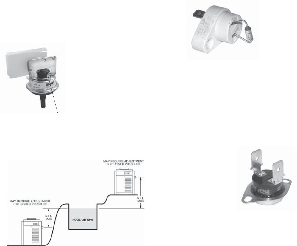
PRESSURE SWITCH
The pressure switch, or heater actuator, insures that
the heater operates only when the filter pump is in
operation. It is located on the inlet/outlet header. It is
factory set at 1.75 PSI for deck level installations. When
the heater is located below the level of the spa or pool, it
may be necessary to reset the pressure switch to
compensate for the no-flow static head. If it is necessary
to reset the pressure switch, utilize the following proce-
dure:
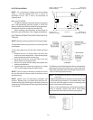
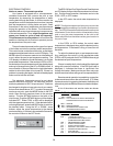
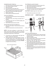
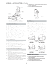
PRESSURE SWITCH ADJUSTMENT
Adjustment
Knob
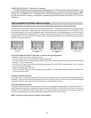
NOTE: If heater is installed outside of the limits shown,
a higher pressure rated (11 psi) switch may be used or a
flow switch mounted and wired adjacent to the heater may
be used in place of the factory mounted pressure switch.
See Parts List for 11 psi pressure switch.
TWO SPEED PUMPS
In some cases, the flow on the low speed is insuffi-
cient to operate the heater. This is apparent when the
pressure switch cannot be further adjusted or if the heater
makes banging noises or goes off on high limit. In these
cases, the pump must be run at high speed when heating
the water.
CAUTION: Do not operate the heater without the function
of a properly adjusted pressure switch or flow switch.
Fig. # 8152.1
PRESSURE SWITCH
ADJUSTMENT RANGE
Fig. #9440
1. With pump and heater on,
turn adjustment knob
(clockwise) until a click is
heard from the gas valve.
2. Turn adjustment knob
(counter clockwise) 1/4
turn.
3. Turn pump off and on several
times. Heater should shut
off immediately. If it does
not, repeat steps above until
proper adjustments made.
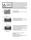
Fig. # 9439
1. Shut off main electrical
power switch to heater.
2. Remove inlet/outlet in-
spection panel.
3. Remove defective high
limit and replace with a
new high limit.
4. Replace inspection
panel.
PILOT SAFETY (Millivolt)
The heaters equipped with the standing pilot (millivolt
system), have pilot generators which act as a safety
device to shut off the flow of gas to the main burners and
the pilot burner in case the pilot flame is extinguished.
The pilot burner must be manually relighted to place the
heater in operation again. Refer to the lighting instruc-
tions provided on the heater label.
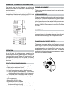
PILOT SAFETY (Electronic)
The heater employs a pilot safety which closes the
main gas valve within 8/10ths of a second whenever the
pilot flame is interrupted. Pilot flame is automatically lit
when the device is powered. Unit performs its own safety
check and opens the main valve only after the pilot is
proven to be lit.
Fig. #9438