


17
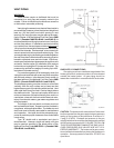
Plumbing from the heater back to the pool must not have
any valves or restriction that could prevent flow when the
pump is operating.
CAUTION: An additional source of heated water, i.e. a
solar system, must be connected to the main line ahead
of the heater inlet pipe in order for it to act as the primary
heat source. If the primary system provides adequate
heat to maintain setpoint, the RP2100 heater will not fire.
Be advised that the RP2100 control panel will then
display sensed water temperatures downstream of the
primary heating system, rather than the temperature of
the water exiting the pool.
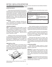
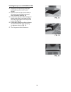
COMPANION FLANGE CONNECTIONS
(CASTIRON HEADER)
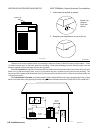
Heater must be located so that any water leaks will not
damage the structure of adjacent area. Hugh temperature
2" plastic pipe (CPVC) may be threaded directly into the
header flanges. This is not the same as the Schedule 80
PVC pipe which is also colored gray. PVC may be used
immediately after the CPVC adapters.
CAUTION: NEVER install PVC directly into header
flanges. Use the 2" CPVC adapter supplied loose with the
heater.
DO NOT use petroleum base assembly fluids (such
as Petroleum Jelly or lubricating oil). If assembly lube is
required, use a silicon base such as Amoral etc.
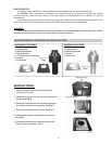
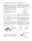
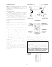
There are two sets of flange gaskets supplied with
your heater. Use the appropriate gaskets for all your
heater connections. Discard unused set.
GASKET DESIGN #1: Accepts 1-1/2" copper tube or
1-1/4" galvanized pipe as a slip connection.
GASKET DESIGN #2: Accepts 2" copper tube as a slip
connection. The flange is threaded for 2" screw in pipe
connections. Also used with the 2" CPVC adapters.
#1 #2
Fig. # 8095.1
Fig. # 8097.1
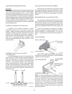
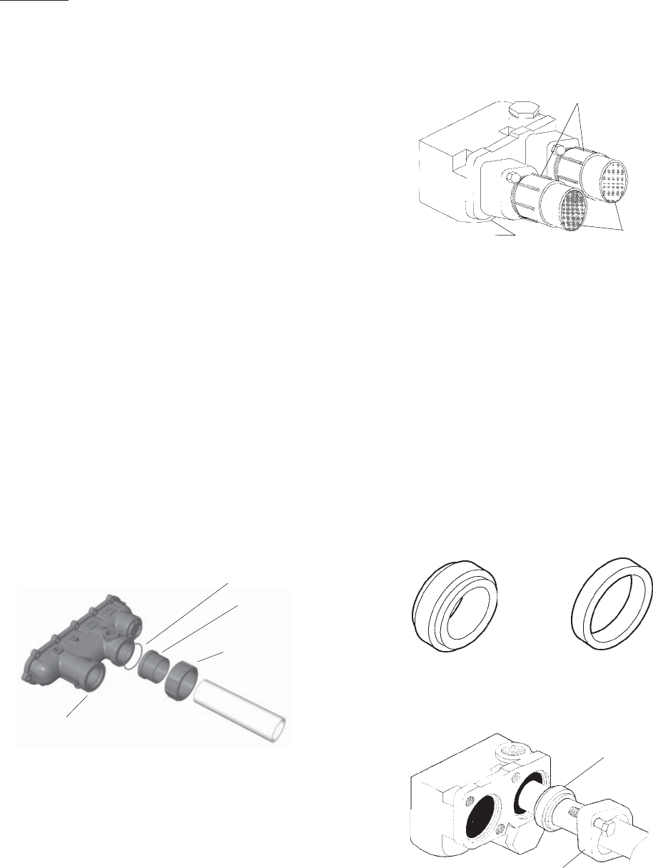
INLET/OUTLET HEADER
2" CPVC Adapters
PVC Pipe
Inlet/Outlet Header
Flange Gasket
Header Flange
Fig. # 8093.1
Heater must be located so that any water leaks will not
damage the structure of adjacent area. PVC pipe may
be glued directly into header unions.
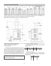
FLOW RATES
MODEL PIPE SIZE MIN.GPM *MAX.GPM
185 1-1/4"-1-1/2" - 2 20 125
265 1-1/4"-1-1/2" - 2 25 125
335 1-1/4"-1-1/2" - 2 35 125
405 1-1/4"-1-1/2" - 2 40 125
*When flow rates exceed maximum GPM an external
auxiliary bypass valve is required. See external bypass
valve section for details.
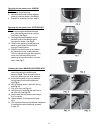
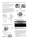
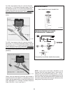
CONNECTIONS (PLASTIC HEADER)
Before attaching the 2-inch unions to the inlet/outlet
header, make sure the o-rings are properly seated in the
grooves. Use AquaLube or equivalent non-petroleum
based lubricant on the o-ring. Tighten the unions hand
tight. Glue PVC piping directly to the unions.
INLET/OUTLET HEADER
Flange Gasket
Header Flange
(CPVC)
Fig. #2002.1
High temperature CPVC Header Flanges and header
Flange Nuts are provided. If there is any possibility of
back- siphoning when the pump stops, it is suggested
that a check valve (or valves) also be installed in the
system.
Header Flange Nut
(CPVC)
Inlet