


25200-2653
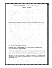
Engine spark plugs are an important part of the
engine ignition system. Worn or incorrectly adjusted
spark plugs can negatively affect engine starting and
operation. Therefore, it is important to inspect and regap,
or replace the engine spark plugs as indicated in the
service interval table. The listed steps are recommended
to access and service the engine spark plugs.
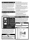
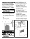
1. Access the spark plugs (J) by removing the front
and back generator panels (K). Insert the key (L)
into the top locks and turn 1/4 turn counterclockwise
to unlock. Lift the panels up and out of the base and
set them aside. Note: there is no need to turn the
locks located on the bottom of the panel.
2. Pull the spark plug boots loose, then clean any dirt
from the area around the spark plugs. Remove the
spark plugs with a 5/8" spark plug wrench.
3. Inspect the spark plugs for fouling or abnormal wear
like excessively worn electrodes or cracked or
chipped insulator material. If abnormal wear is
indicated, replace the spark plugs. Fouled plugs
indicate the need for engine service by a qualified
engine service technician.
New spark plugs or plugs that do not display any
abnormal characteristics should be checked for
proper gap using a suitable spark plug gauge.
Adjust the gap to .035 inches (.889 mm) by carefully
bending the grounding electrode.
4. Reinstall the spark plugs by hand until they begin to
seat to avoid cross-threading. After the plugs begin
to seat, tighten plugs an additional ¼ turn with a
5/8" spark plug wrench to avoid damage to the
spark plugs. If a torque wrench is available, tighten
all plugs to 13 in-lbs (18 N-m).
5. Reassemble the front and back panels (K) to the
generator by setting the bottom end of the panel into
the base and push into place. Insert the key (L) into
the top locks and turn 1/4 turn clockwise to lock.
BB
BB
AA
AA
TT
TT
TT
TT
EE
EE
RR
RR
YY
YY
MM
MM
AA
AA
II
II
NN
NN
TT
TT
EE
EE
NN
NN
AA
AA
NN
NN
CC
CC
EE
EE
((
((
cc
cc
oo
oo
nn
nn
tt
tt
..
..
))
)
)
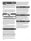
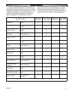
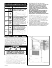
Table A
Display Operating Condition
Red
•When the red LED is on, it indicates that
your battery is discharged and the charger
is recharging at the "BULK" rate of 6
Amps. •While the red LED is on, the
voltage measured will be 11.8 to 14 volts.
•If the red LED stays on for more than 24
hours, refer to the troubleshooting section
of this manual.
Green
Red
•When both the green and the red LED's
are on, the charger is charging at an
"ABSORPTION" rate of between 1.5 and 5
Amps. This mode of charging gradually
"tops off" the battery, and reduces harmful
sulfating. •While both LED's are on, the
voltage measured should be approx. 14.0
to 14.5VDC. •If both LED's stay on longer
than 24 hours, refer to the troubleshooting
section in this manual.
Green
Red
•When the green LED is on, the charger is
charging at a "FLOAT" rate of less than
1.5 Amps. •This "float" charging current
will gradually decrease to as low as 0.1
Amps as the battery reaches 100%
charge. It will now be kept at full charge
without over-charging. •If the green LED
stays on when the battery is known to be
low, refer to the troubleshooting section of
this manual.
Green
SS
SS
PP
PP
AA
AA
RR
RR
KK
KK
PP
PP
LL
LL
UU
UU
GG
GG
CC
CC
HH
HH
EE
EE
CC
CC
KK
KK
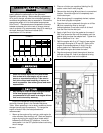
WWAARRNNIINNGG
• Before performing any maintenance, make sure
the Mode switch is in the OFF position, the
circuit breaker is in the OFF position and the
positive (red) battery cable is disconnected.