


200-265314
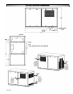
After electrical connections are complete, the next
installation step is to connect a fuel supply to the unit.
The fuel inlet fitting supplied with the generator is male
3/4" NPT. To accommodate potential settling of the
generator relative to rigid supply pipeline, use of a
flexible line, provided by manufacturer, in the supply line
is suggested. When making connections, use only
materials rated for the fuel supplied and approved for use
by local, regional or national codes and/or regulatory
agencies.
Units are tested with natural gas before they leave
the factory. If natural gas is to be used, no adjustments
are required.
When supplying natural gas as the operating fuel,
provide fuel with a minimum of 1000 BTU/ft
3
at inlet
pressures between 6" and 11" of water column (4 - 6
oz). Failure to meet these minimums will cause the
generator to run poorly and/or may limit output to values
below nameplate value. If fuel with these qualities is not
available, contact the customer service center.
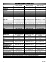
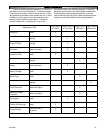
Refer to the Fuel Consumption Table on page 13 for
fuel flow requirements for the unit installed. Size all
feeding piping to deliver sufficient flow above the
minimum pressure of 6" water column (4 oz).
Per the National Gas Code (NFPA 54 - ANSI
2223.1), a manual shutoff valve in the fuel supply line
to the generator is recommended.
In cases where liquefied propane vapor is selected
as the fuel of choice, the following steps need to be
followed for hookup.
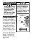
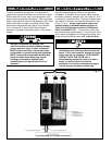
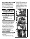
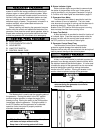
Engine Timing for LP
1. Connect timing light to spark plug wire #1, power
leads to 12V DC power source(FIG 1).
2. Loosen hold down clamp bolt on distributor (FIG. 2).
NOTE: DO NOT REMOVE!
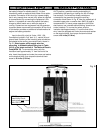
3. Start generator - ensure all wires from timing light are
free from all moving parts.
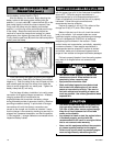
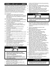
4. While generator is operating in a no load condition
use timing light to obtain engine timing (FIG. 4).
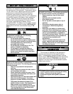
5. Rotate distributor cap (FIG. 3) slowly to obtain timing
of 26 degrees BTDC(36 degrees BTDC for natural
gas).
6. Retighten hold down clamp bolt (FIG. 2) - DO NOT
MOVE DISTRIBUTOR CAP WHILE
RETIGHTENING BOLT.
7. Reverify timing after tightening hold down clamp.
FF
FF
UU
UU
EE
EE
LL
LL
HH
HH
OO
OO
OO
OO
KK
KK
UU
UU
PP
PP
Natural Gas (NG)
DDAANNGGEERR
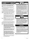
• All fuel system installations MUST BE done by a
licensed plumber or licensed gas technician
and must comply with all applicable codes,
standards and regulations.
WWAARRNNIINNGG
• Natural Gas and Propane Vapor are highly
explosive gases. Check ALL
fuel system
connections for leaks before starting
engine/generator set.
• DO NOT use a flame to check for leaks.
• Use approved equipment and methods to check
for leaks.
Propane Vapor (LPG)
FIG. 1
FIG. 2
FIG. 3
FIG. 4