


-- 3 --
plug disconnected. Keep vents and dis-
charge tubes free of debris which can ac-
cumulate and restrict proper air flow.
D Never place any object in the air intake
opening as this could restrict p roper air f low
and cause damage to th e u nit.
D Never use for spreading chemicals, fertil-
izers, orother substanceswhichmay con-
tain toxic materials.
D To avoid spreading fire, d o not use near
leaf or br ush fires, fireplaces, barbecue
pits, ashtrays, etc.
D Use only forjobs explained inthis manual.
MAINTAIN YOUR UNIT PROPERLY
D Have all maintenance o ther than the rec-
ommended procedures described in thein-
struction manual performed by an autho-
rized service dealer.
D Disconnect spark p lug bef ore performing
maintenance except for carburetor adjust-
ments.
D Use only recommended Poulan PROR re-
placement parts; u se of any other parts
may voidyour warranty an dcausedamage
to y our unit.
D Empty f uel t ank be fore storing the unit. Use
upfuelleft incarburetor by starting engineand
letting it run unt il it stops.
D Do not use a ny a ccessory or a tta chment
other than those r ecommended by manuf ac-
turer for use with your unit.
D Do notstore the unit orfuel ina closed area
where fuel vapors can reach sparks or an
open flame from hot water heaters, electric
motors or switches, furnaces, etc.
D Store in a dry area out of reach of c hildren.
SPECIAL NOTICE: Exposure to vibra-
tions through prolonged use of gasoline pow-
ered hand tools could cause blood vessel or
nerve damage in the fingers, hands, and
joints of peopleprone to circulation disorders
or abnormal swelling. Prolonged use in cold
weatherhas beenlinked tobloodvesseldam-
age inotherwise healthy people.If symptoms
occur such as numbness, pain, loss of
strength, change in skin color or texture, or
loss of feeling inthe fingers, hands , or joints,
discontinue the use of this tool and seek
medical attention. An antivibration system
does not guarantee the avoidance of these
problems. Users who operate power tools on
a continual and regular basis must m onitor
closely theirphysical conditionand thecondi-
tion of this tool.
SPECIAL NOTICE: Fo r users o n U.S. For-
est Land and in some states, including Cali-
fornia (Public Resources C ode s 4442 and
4443), I daho,Maine, Minnesota,New Jersey,
Oregon, and Washington: Certain internal
combustion engines operated on forest,
brush,and/orgrasscovered landin theabove
areas are required to be e quipped w ith a
spark arresting screen, maintained in effec-
tive working order, orthe enginemust becon-
structed, equipped, and maintained for t he
prevention of f ire. Check with yourstate or lo-
cal authorities for regulations pertaining to
these requirements. Failure to follow these
requirements is aviolationof thelaw. Thisunit
is not factory equipped with a spark arresting
screen; however, a spark arresting screen is
available asan optionalpart. Ifa spark arrest-
ing screen is required in your area, contact
your authorized service dealerfor the correct
kit. The spark arrestingscreen, blower tubes,
and nozzles must be assembled to unit to be
in full compliance with regula ti ons.
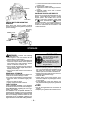
ASSEMBLY
WARNING: S top engine and be sure
the impeller blades have stopped turning be -
fore opening the vacuum inlet door or at-
tempting to insert or remove the vacuum or
blower tubes. The rotating blades can cause
serious injury. Always disconnect the spark
plug before performing maintenance or ac-
cessing movable parts.
WARNING: If you receive your unit
assembled, c heck each step to insure your
unit is properly assembled and all fasteners
are s ecure. Follow all safety infor m ation in
the manual and on the unit.
D A standard screwdriver is required for as-
sembly.
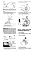
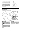
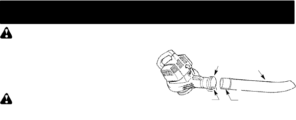
BLOWER TUBE ASSEMBLY
1. Align the rib on the blower tube with the
groove in the blower outlet; slide the tube
into place.
NOTE: Knob m ustbe loose enoughto allow
blower tube to be inserted in blower outlet.
Loosen knob by turning counterclockwise.
Blower
Tube
Blower
Outlet
Rib
Groove
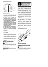
2. Secure thetubeby turningthe knobclock-
wise.
3. Toremove t hetube,turn theknobcounter-
clockwise to loosen the tube; remove the
tube.
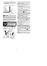
VACUUM BAG ASSEMBLY
1. Open the zipper on the vacuum bag and
insert the elbow tube.
2. Push the small end of the elbow tube
through the small opening in the bag.