


7
Wing Nut
Bracket
Slot
Shield
Gearbox
PIVOT
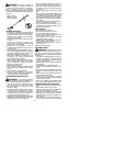
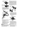
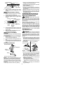
ASSEMBLY INFORMATION -- WEED
BLADE
WEED
BLADE
NOTE:
Remove the trimmer head and plastic
shield befo re attaching t he metal shield and
in stallin gthe weedb lade.Toremov ethetrimm er
head, align hole in the dust cup with the hole in
the side of the gearbox by rotating t he dust cup.
Insert a small scre wdriver into aligned holes.
This will keep the shaf t from tu r ning while loos-
ening the trimmer head. Remove the trimmer
head by turning clockwise. Remove the screw-
driver. To remove the plastic shield, loosen and
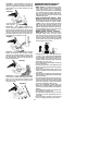
remove win g nut. Pivotshieldto releasebracket
from slot. See INST ALLATION OF THE TRIM-
MER HEAD and ATT ACHING T HE PLASTIC
SHI E LD for illust r atio ns. Be sure to store a ll
parts and instructions for futu re use. Never use
t he trim m er head with the m eta l blad e ins ta lled.
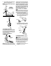
ATTACHING THE METAL SHIELD
W ARNING:
The metal shield must be
properly installed on the tool anytime the tool
is used with a blade. The forward tip o f the
metalshield helpstoreducetheoccurrenceof
blade thrust which can cause serious injury
such as amputation to the operator or by-
standers. Failure to install the shield in the
position shown can result in serious injury to
the operator. Thelength of the shield must be
aligned with the length of the shaft.
1. Place the metal shield under the gearbox,
and align the screw holes.
Shield
Gearbox
2. Insert and thread the 4 mounting screws
throughthe holes of the gearbox and the
metal shield. Tightenevenly andsecure-
ly with the hex wrench provided.
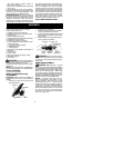
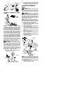
INSTALLATION OF THE M ETAL
BLADE
W ARNING:
Wear protective gloves
when handling or performingmaintenanceon
the blade to avoid injury. The blade is sharp
and can cut you even when it is not moving.
W ARNING:
Do not use any blades, or
fastening ha rdware other th an the washers a nd
n ut s shown in the follow in g illu strations. T hese
parts must be provided by Poulan/Weed Eater
and installed as shown below . Failure to use
proper parts can cause the blade to fly off and
seriously hu rt you or ot hers.
NOTE:
The dust cup and retaining washerare
locate d on thegearbox shaftand not in the parts
bag. All othe r fasteners mentioned in the follow-
ing assembly steps are in t he parts bag.
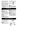
1. Remove the retaining wa sher from the
threade d shaft of the g earbox. Leave the
d ust cup on the shaf t .
2. Install the blade and the retaining washer
over the threaded shaft.
3. Make sure the raised part of the retaining
washer is facing thegearbox and the raised
area fits into the hole in the cente r of the
blade.
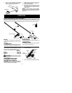
4. Slidethebladeandretainingwasheronto
the shaft of the gearbox.
5. Place the cupped washer onto the shaft.
Makesurethecupped sideof thewasher
is toward the blade.
6. Install theblade nutby threadingontothe
shaft counterclockwise.
Shield
Blade
Retaining
Washer
Dust Cup
Cupped
Washer
Nut
Threaded Shaft
Gearbox
NOTE:
Ma kesureall par tsa r einpla ceasillu s-
trated, a nd th e b lade is sandwichedbetween the
dust cup andthe retaining washer . There should
be nospace between t heblade andthedust cup
or the retaining washer .
7. Align h ole in dust cup with hole in side of
gea rbox b y rotating the blade.