


4
from water heaters, electric motors or
switches, furnaces, etc.
S
Store unit so the blade cannot accidentally
cause injury.
S
Store unit indoors, out of reach of children.
If situations occur which are no t co vered in this
manual, use care and good judgment. If you
need a ssistance, call 1--800--554--6723.
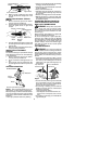
SPECIALNOTICE:
Exposuretovibrations
through prolonged use of gasoline powered
hand tools could cause blood vessel ornerve
damage in the fingers, hands, and joints of
peoplepronetocirculationdisorders orabnor-
mal swellings. Prolonged use in cold weather
has been linked to blood vessel damage in
otherwise healthy people. If symptoms occur
such as numbness, pain, loss of strength,
changein skin color or texture, orloss offeel-
ing in thefingers,hands,or joints, discontinue
theuseofthistool andseekmedicalattention.
An anti-vibration system does not guarantee
the avoidance of these problems. Users who
operatepowertoolson acontinualandregular
basis must monitor closely their physical
condition and the condition of this tool.
SAVE THESE INSTRUCTIONS
ASSEMBLY
CARTON CONTENTS
Check carton contents for the following:
S
Brushcutter attachment
S
Handlebar (with clamp and knob)
S
Handlebar clamp base (with spacer tabs)
S
Shoulder strap
S
Upper shoulder strap clamp
S
Lowershoulderstrap clamp (with spacer tab s)
S
Handlebar clamp screws (4)
S
Shoulder strap clamp screws (2)
S
4--point weed blade (assembled on brush-
cutter attachment)
S
Largenut for installing blade
S
Retaining washer
S
Cupped washer
S
Metal shield (assembled on brushcutterat-
tachment)
S
Trimmer head
S
Plastic shield
S
Wing nut (screwed onto plastic shield)
S
Attachment hanger
S
Hex wrench
W ARNING:
If received assemble d, re-
peat all steps to ensure your unit is pro perly as-
sembled and all fastene rs are secure.
Examine parts for damage. Do not use dam-
aged parts.
NOTE:
Ifyouneedassist anceorfin dt ha tpar ts
are missing or damaged, call 1-800-554-6723.
TOOLS REQUIRED
S
Hex wrench (provided)
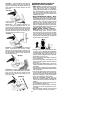
INSTALLING BRUSHCUTTER
ATTACHMENT
CAUTION:
Wh en re movin g or inst allin g at-
tachments, p lace the u nit on a flat surface for
st ability.
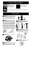
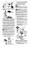
1. Loosen the coupler by turning the knob
counterclockwise.
Coupler
Knob
LOOSEN
TIGHTEN
2. Removethe shaftcap from thebrushcut-
ter attachment (if present).
3. Position locking/release buttonof attach-
ment into guide recess of coupler.
4. Pushtheattachmentintothecoupleruntil
the locking/release buttonsnaps into the
primary hole.
5. Beforeusingthe unit,tightentheknobse-
curely by turning clockwise.
Coupler Primary Hole
Upper
Shaft
Locking/
Release
Button
Lower
Attachment
Guide Recess
W ARNING:
Make sure thelocking/re-
lease button is locked in the primary hole and
the knob is securely tightened before operat-
ing the unit.
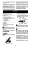
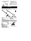
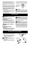
HANDLEBAR ASSEMBLY
DANGER:
RISK OF CUT.
To avoid
seriousinjury,thebarrier portionof thehandlebar
must be installed as shown on the upper shaft of
the powerhead to provide a barrier between op-
erator and the spinning blade. Attach shaft
clamp above arrow on safety warning decal on
the u ppershaft ( powerhead en d o f unit). Ensure
handlebar is positioned on ha ndlebar clamp be-
tween the arrows on the handlebar decal.
NOTE:
The shaft clamp base has four
spacer tabs attached. These tabs are pro-
vided to adapt this attachment for use with
powerheads that have a 1
"
diameter upper
shaft(theshaftclampwill nottightendownse-
curely on the 1
"
diameter upper shaft without
using these spacer tabs). The tabs must be
broken off completely before use and placed
over the screw holes on the clamp base.
These tabs are not needed for powerheads
with a 7/8
"
upper shaft.