


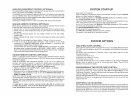
SETTING
THE
CLOCK
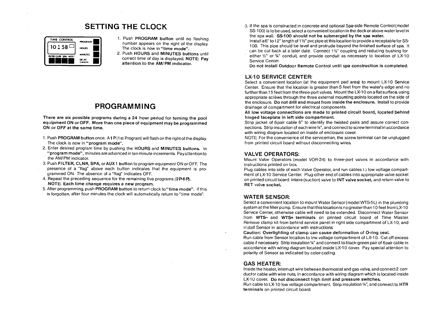
1. Push PROGRAM button until no flashing
number appears on the right of the display.
The clock is now in
"time mode".
2. Push HOURS and MINUTES buttons until
correct time of day is displayed NOTE: Pay
attentinn
to the AM/PM indicator.
PROGRAMMING
There are six possible programs during a 24 hour period for turning the pool
equipment ON or OFF. More than one piece of equipment may be programmed
ON or OFF at the same time.
1. Push PROGRAM button once
A1 P(l st Program) will flash on the right of the display.
The clock is now in "program mode".
2. Enter desired program time by pushing the HOURS and MINUTES buttons In
"program mode", minutes are advanced in ten minute increments
Pay~ttention to
the
AWPM indicator.
3.
Push FILTER, CLNR, SPA, orAUX1 button to program equipment ON or OFF. The
presence of a "flag" above each button indicates that the equipment is
pre
grammed ON. The absence of a "flag" indicates OFF.
4. Repeat the preceding sequence for the remaining five programs
(2P6P).
NOTE: Each time change requires a new program.
5. After programming, push PROGRAM button to return clock
toL'time mode". If this
is forgotten, after four minutes the clock will automatically return to "time mode".
3.
If the spa is constructed in concrete and optional Spa-side Remote Control (model
SS-100) is to be used, select a convenient location in the deck or above water level in
the spa wall
SS-100 should not be submerged by the spa water.
Install
a6" to 12" length of 1
%"
pvc pipe at this location to provide a receptable for SS
100. This pipe should be level and protrude beyond the finished surface of spa
It
can be cut back at a later date. Connect 1
l/2"
coupling and reducing bushing for
'
either
%"
or
%"
conduit and provide conduit as necessary to location of LX-10
Service Center.
Do not install Outdoor Remote Control until spa construction is completed.
U-10
SERVICE CENTER:
Select a convenient location (at the equipment pad area) to mount LX-10 Service
Center. Ensure that the location is greater than
5
feet from the water's edge and no
further than 15 feet from the
threeport valves Mount the LX-10 on a flat surface, using
appropriate
scr'ews through the three external mounting points located on the side of
the enclosure. Do not drill and mount from inside the enclosure. Install to provide
drainage of compartment for electrical components
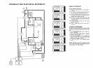
All low voltage connections are
mads to printed circuit board, located behind
hinged faceplate in left side
compartment.
Strip jacket of Gpair cable
6"
to identify the twisted pairs and assure correct cop
nections Strip insulation of each wire
Y4",
and connect to screw terminal inaccordance
with wiring diagram located on inside of enclosure cover.
NOTE For the convenience of the serviceman, the screw terminal can be unplugged
from printed circuit board without disconnecting wires
VALVE OPERATORS:
Mount Valve Operators (model VOR-24) to threeport valves in accordance with
instructions printed on box
Plug cables into side of each Valve Operator, and run cables
t~ low voltage compart-
ment of
LX-10 Service Center. Plug other end of cables into appropriate valve socket
on printed circuit board:
intake(suction) valve to INT valve socket, and return valve to
RET
.~alve socket
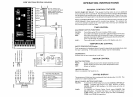
WATER SENSOR:
Select a convenient location to mount Water Sensor(mode1 WS5L) in the plumbing
system at the filter pump Ensure that thislocation is nogreaterthan 10 feet from LX-10
Service Center, otherwise cable will need to be extended Disconnect Water Sensor
from
WTS-
and
WTSe
terminals on printed circuit board of Time Master.
Remove clamp kit from behind service panel in right side compartment of LX-10, and
i~stall Sensor in accordance with instructions
Cautior.: Overtighting of clamp can cause deformation of Oring seal.
Run cable from Sensor
I~ation to low voltage compartment of LX-10. Cut off excess
cable
if
necessary. Strip insulation
l/4"
and connect to black-green pair of 6pair cable in
acco:dance with wiring diagram located inside LX-10 cover. Pay special attention to
polarity of Sensor as indicated by color-coding.
GAS HEATER:
Inside the heater, interrupt wire between thermostat and gas valve, and connect2 cop
ductor cable with wire nut% in accordance with wiring diagram which is located inside
LX-10 cover. Do not disconnect high limit and pressure switches
Run cable to LX-10 low voltagecompartment Strip insulation
%",
and connect to HTR
terminals on printed circuit board