


AUXILIARY EQUIPMENT CONTROL (OPTIONAL):
SYSTEM START-UP
The standard Time Master system is provided with 3 power relays for controlling filter
pump, pool cleaner, and auxiliary 1 (pool light).
It is possible to control additional equipment (such as a jet pump, air blower, spa light,
etc) by installing extra relay kits (model RLY-LX). The LX-10 Service Center will
accommodate a total of 7 relays Note: Further relays may be controlled by an addt
tional Power Center (model
LX-36).
lnstall RLY-LX Relay Kit at the LX-10 in accordance with instructions provided.
SPAaSIDE REMOTE CONTROL (OPTIONAL):
When the spa construction is completed, install optional Spa-side Remote Control
(model
SS100) in accordance with instructions provided:
1. Cut back the
11/2" dia pvc receptacle flush with spa wall finish or surface of deck
2.
Making sure that screw threads are facing out, glue adapter into receptacle using
pvc cement
3. Thread cable through gasket, and run through conduit to LX-10
low voltage
compartment
4. Before installing SS-100, rotate 7 turns counterclockwise to avoid undue twisting
of cable
5. Screw
SS100 into adapter and finger-tighten. Caution: Do not use wrench
6.
At the LX-10, cut off excess cable
if
necessary. Strip insulation
'/a",
and make
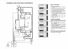
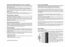
connections to REMOTE SWITCHES screw terminals in accordance with
wiring diagram located inside enclosure cover.
Connect black wire (switch common) to GND terminal, and connect red, yellow,
and green wires to desired terminal for
SPq AUX 1, AUX
2,
AUX
3
and AUX
4.
Note: for the convenience of the serviceman, the screw terminal can be unplugged
from printed circuit board without disconnecting wires
INDOOR REMOTE CONTROL (OPTIONAL):
Select a convenient location inside the house or other weather-protected area to
mount the LVS-3(3 button indoor remote) or
LVSSTR(3 button indoor remote w/ digital
temperature display).
Install in accordance with instructions provided At the
LX-10 low voltage con
partment, strip jacket of cable
6"
to identify the twisted pairs and assure correct
connections Strip insulation of each wire
'/4",
and connect to appropriate screw
terminals at REMOTE SWITCHES and REMOTE LAMPS terminal:
1. Select any three circuits from SPA, AUX 1, AUX
2,
AUX
3,
and AUX
4.
2. Number the circuits 1,
2,
and 3.
3. Make sure that the corresponding SW and LMP wires from the Indoor Remote are
connected to the appropriate circuit at the LX-10 REMOTE SWITCHES and
REMOTE LAMPS terminal.
NOTE:
If
the LVS3TR is being used install the second Water Sensor (included) in
accordance with previous instructions and run cable to LX-10 low voltage con
partment Wire nut to yellowblack pair of wires from LVS-3TR cable (red connects to
yellow, green connects to black), in accordance with wiring diagram located inside
LVS-3TR
A Label
Set for indoor remote controls (model LBL-100) is available from
Compool Corporation. This set of
100
different labels provides custom equip
ment identification at each remote control button.
Apply power to the system.
At
theTime Master, pullout batteryshield toactivate back-up battery, and push HOURS
button until digital readout is displayed
At the LX-10 Service center, turn SYSTEM CONTROL Switch
to"SERV1CE position
and FLOW CONTROL Switch to "POOL" position.
Check that Valve Operators have rotated to correct positions
Toadjust position of any
valve, simply reverse the cable plug on the side of Valve Operator.
At the LX-10 Service Center, turn MANUAL CONTROL Switches to "ON positions
and check that all equipment is operating.
Turn OUTDOOR
REMOTES Switch to"ONn position and check that optional Spa-side
Remote Control is functioning correctly.
Turn MANUAL CONTROL Switches
to"OFF1 positions
The system is now ready to be operated as desired
SYSTEM OPTIONS
TWO SPEED PUMP CONTROL:
If the system is equipped with a two speed filter pump, a Dual Speed Relay Kit (model
RLY-LXD) should be added at the LX-10 in accordance with installation instructions
provided
The system will automatically run the filter pump in high speed under any of the
following conditions
1. Whenever the heater is on
2. Whenever pool cleaner is running
3. Whenever spa is running
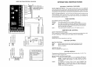
It is possible to eliminate one or more of these conditions by adjusting
U11 Program
Switch, which is located at the top of the printed circuit board See RLY-LXD
installation instructions for details
PROGRAMMABLE TWO SPEED PUMP CONTROL:
If the system is equipped with a two speed filter pump, it is additionally possible to
program the pump to run in high speed by using AUX
1
Program Button on the
Time Master Controller. However, this feature will only operate when the filter pump is
running Install RLY-LXD as above.
Adjust
U10
Program Switch (located at the bottom of the printed circuit board) so that
Switches #1,
#3 and
#6
are programmed ON, and Switches #2, #4, #5, and #7 are
programmed OFF.
ADDITIONAL VALVE CONTROL:
It is possible to add valve operators(mode1 VOR-24) to the system to actuate additional
threeport valvesfor pool cleaning or for a custom hydraulic feature(such as a fountain,
waterfall second spa, etc). A total of three valve operators may be added. Install Valve
Module (model
MODVLV1) at LX-10 low voltage compartment in accordance with
instructions provided, and connect valve operators accordingly.