


P/N 472235 Rev. E 4-15-05
8
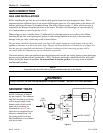
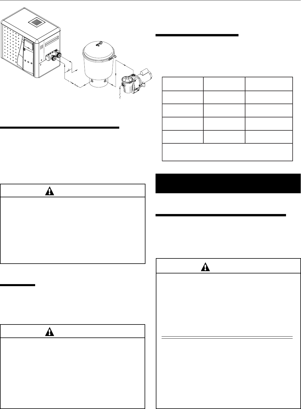
PUMP
FILTER
POOL
HEATER
CHECK
VALVE
MANUAL
BY-PASS
TO
POOL
GATE
VALVE
CHECK
VALVE
FROM
POOL
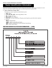
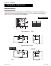
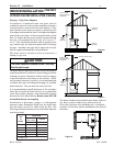
Figure 2.
PLUMBING CONNECTIONS
The MiniMax NT heater has the unique capability of direct
schedule 40 PVC plumbing connections. A set of bulkhead
fittings is included with the MiniMax NT to insure
conformity with Pentair’s recommended PVC plumbing
procedure. Other plumbing connections can be used. See
Figure 2 for plumbing connections.
CAUTION
Before operating the heater on a new installation, turn
on the circulation pump and bleed all the air from
the filter using the air relief valve on top of the filter.
Water should flow freely through the heater. Do not
operate the heater unless water in the pool/spa is at
the proper level. If a manual by-pass is installed,
temporarily close it to insure that all air is purged
from the heater.
VALVES
When any equipment is located below the surface of the
pool or spa, valves should be placed in the circulation piping
system to isolate the equipment from the pool or spa. Check
valves are recommended to prevent back siphoning.
CAUTION
Exercise care when installing chemical feeders so
as to not allow back siphoning of chemical into the
heater, filters or pump. When chemical feeders are
installed in the circulation of the piping system,
make sure the feeder outlet line is down stream of
the heater, and is equipped with a positive seal
noncorrosive “Check Valve”, (P/N R172288),
between the feeder and heater.
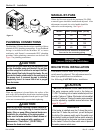
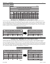
ledoM)MPG(.niM*)MPG(.xaM
00202021
05203021
00303021
00404021
dednemmocermumixamehtdeecxetonoD*
.gnipipgnitcennocehtrofetarwolf
MANUAL BY-PASS
Where the flow rate exceeds the maximum 120 GPM,
a manual bypass should be installed and adjusted. After
adjustments are made, the valve handle should be
removed to avoid tampering. See Figure 2.
BELOW POOL INSTALLATION
If the heater is below water level, the pressure
switch must be adjusted. This adjustment must be
done by a qualified service technician.
See following CAUTION before installation.
CAUTION
BELOW OR ABOVE POOL INSTALLATION
The water pressure switch is set in the factory at
1½ PSI. This setting is for a heater installed at pool level
or within 3’ above or 3’ below. If the heater is to be installed
more that 3’ above or 3’ below, the water pressure switch
must be adjusted by a qualified service technician. See
page 22, Figure 22.
FLOW SWITCH
If the heater is installed more the 6’ above the pool or
more than 10’ below the pool level, you will be beyond
the limits of the pressure switch and a flow switch must
be installed. Locate and install the flow switch externally
on the outlet piping from the heater, as close as possible
to the heater. Connect the flow switch wires in place of
the water pressure switch wires.
Section III. Installation
Table 1.
See page 30 for
Pressure Relief Valve Installations.