Rev. E 4-15-05 P/N 472235
23
SAFETY CONTROLS, (cont’d.)
HIGH LIMITS
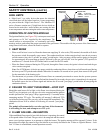
A “High Limit”, is a safety device that opens the electrical
circuit and shuts off the heater based on a water temperature
set point within the “High Limit Device”. The MiniMax NT
series of heaters contains two (2) high limit devices which are
located on the main inlet / outlet header, one sensing the inlet
water temperature and one sensing the outlet water temperature.
OPERATION OF IGNITION MODULE
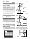
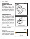
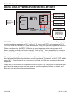
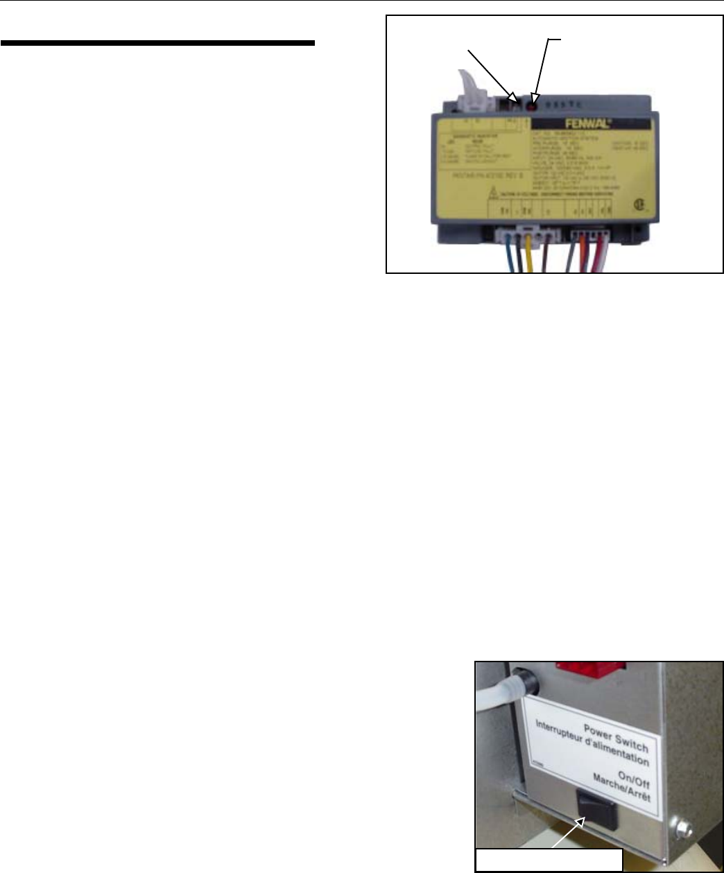
The Ignition Module, (see Figure 24), is microprocessor based
and operates on 24 VAC supplied by the transformer. The
control utilizes a microprocessor to continually and safely
monitor, analyze, and control the proper operation of the gas burners. The module with the presence of the flame sensor,
using flame rectification, allows the heater to operate.
1. HEAT MODE
• When a call for heat is received from the thermostat supplying 24 volts to the (TH) terminal, the module will check
the pressure switch for normally open contact. The combustion blower is then energized and, once the air pressure
switch contacts close, the 15-second "pre-purge" period begins. After pre-purge, the hot surface igniter is energized
for approximately 40-second heat-up period, followed by the gas valve for the "trial for ignition" (TFI) period, for
maximum of 7 seconds for the STD model and 6 seconds for the TSI model.
• When the flame is detected during the TFI period, through the flame sensor, the igniter is deactivated and the gas
valve remains energized.
Note: For all TSI heaters: After the pre-purge period the combustion blower slows down to half normal speed during
the heat-up and TFI periods and continues thereafter for another 30 seconds at low speed, then return to full speed
for the remainder of the heating cycle.
• The thermostat, air pressure switch and burner flame are constantly monitored to assure that the system operates
properly. When the thermostat is satisfied and the demand for heat ends, the gas valve is immediately de-energized,
the module senses the loss of flame signal and initiates the 45-second "post-purge" period before de-energizing the
combustion blower.
2. FAILURE TO LIGHT THE BURNER—LOCK OUT
Should the main burner fail to light, or the flame is not detected during the
first TFI (try for ignition) cycle, the gas valve is de-energized and the ignition
module performs an "inter-purge" delay (approximately 15 seconds) before
attempting another TFI cycle. The module will attempt 2 additional TFI's
cycles before locking out. The gas valve will be turned off immediately. The
combustion blower will be turned off following 45 seconds "post-purge"
period.
The module will automatically reset after one hour, if the thermostat
is still calling for heat, and attempt a new TFI cycle.
3. FLAME FAILURE—RE-IGNITION
If the established flame signal is lost while the burner is operating, the control
will respond within .08 second. The gas valve is de-energized and the control
starts a new ignition sequence in an attempt to relight the burner. The ignition attempt will be repeated (3) times. If the
burner does not relight, the control will go into lockout as previously described in the “Failure to Light the Burner—Lock
Out”. If flame is reestablished, normal operation resumes.
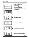
Diagnostic LED
1 Flash - Air Flow Fault
2 Flashes - Flame no Call for Heat
3 Flashes - Lock Out
Flame Current
Check Point
Section IV. Operation
Figure 24.
Figure 25.
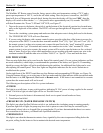
INTERNAL POWER SWITCH


