


(d) Overcrank circuit; will stop automatic cranking and
indicate overcrank if engine fails to start after 3 attempts.
The number of cranks are selectable for 1, 2, 3, 4 or 5
cycles before shutdown. The overcrank circuit may also
be turned off so no overcrank shutdown occurs.
(e) Shutdown Time Delay Bypass; this delay prevents the oil
pressure, water temperature and loss of speed signal
shutdown circuits from operating for 15 seconds after the
engine starts as detected by the crank disconnect circuit.
This same delay also locks out the Low Oil Pressure Pre-
alarm and High Water Temperature Pre-alarm circuits
when the engine is not running.
(f) Overspeed Speed Switch;
1. Provides a signal to the overspeed shutdown circuit if
the engine exceeds the preset speed. The factory
setting is approximately 3894 Hz, or 1980 RPM on an
engine with 118 teeth on the flywheel ring gear. The
adjustment range is 300 Hz to 10,000 Hz.
2. A push-to-test switch is provided to allow testing of the
overspeed circuit without overspeeding the engine.
When switch is depressed, the set point of the speed
switch is lowered approximately 10%.
3. The push-to-test switch can also be used to set the
overspeed switch at approximately 110% of running
speed. Hold the switch depressed while adjusting the
setting until the overspeed trips. When switch is
released, the set point will be 10% above normal running
speed. This is the method used to make the factory
setting. With engine speed at 1800 RPM or 3540 Hz.
(g) Cooldown circuit; this circuit keeps the engine running
for five minutes after the transfer switch has removed
the load from the generator and signaled the A901 to
stop the engine. This feature may be selected (turned
On, standard setting is Off) with a switch on the back of
the Control / Display Module.
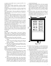
3-2.1.5 Seven (7) First-out Shutdown Circuits; provide first-out
indication of cause of shutdown. These circuits deactivate the
fuel relay and lockout the A901 until reset. Shutdown circuits
are activated by the crank disconnect circuit and are not active
when the engine is stopped. Six (6) Red Shutdown Indicating
Lights are provided. The Remote Shutdown circuit does not
have an indicator light.
(a) Overcrank; tripped by the overcrank sensing circuit which
counts the number of cranking attempts.
(b) Overspeed; tripped by overspeed switch when engine
exceeds a preset speed.
(c) Oil Pressure; tripped by the oil pressure SWICHGAGE
®
if pressure drops below preset point while the engine is
running.
(d) Water Temperature; tripped by the water temperature
SWICHGAGE
®
if engine coolant temperature exceeds the
switch setting.
(e) Spare Shutdown; tripped by an external switch. This
circuit is provided for an additional shutdown that may be
recommended by the engine supplier.
(f) Loss of Speed Signal; tripped by an internal sensing
circuit that detects the loss of the Magnetic Pickup
frequency signal for the speed switches while the engine
is still running. Since the Overspeed shutdown circuit is
activated by the frequency input, it prevents the engine
from running without overspeed protection.
(g) Remote Shutdown; this circuit is provided to shutdown
the engine generator from a remote location. No
indicating light is provided.
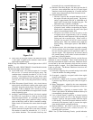
3-2.1.6 Nine (9) Alarm Indicating Circuits; provide indication of
cause of alarm. These circuits activate the alarm relays. Alarm
circuits are active as long as power is applied to the A901. All are
active when the engine is running, shutdown or on standby except
Low Oil Pressure Pre- alarm and High Water Temperature Pre-
alarm. Nine (9) Amber Alarm Indicating Lights are provided.
(a) Low Water Temperature; operated by low water temp-
erature SWICHGAGE
®
.
(b) Spare Alarm; operated by an external switch. This circuit
is provided for an additional alarm that may be required by
the user.
(c) Switch Not In Automatic; operated by the OFF-AUTO-
TEST mode selector switch.
(d) Low Fuel Level; operated by level switch on fuel tank.
(e) High Battery Voltage; operated by relay contact in
battery charger.
(f) Low Battery Voltage; operated by low voltage sensing
device in battery charger.
(g) Low Oil Pressure Pre-alarm; operated by pre-alarm
switch in oil pressure SWICHGAGE
®
.
(h) High Water Temperature Pre-alarm; operated by pre
alarm switch in water temperature SWICHGAGE
®
.
(i) Battery Charger AC Failure: operated by a relay contact in
the Battery Charger.
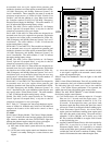
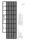
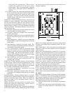
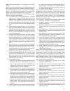
3-2.2 Relay Module. The Relay Module, figure 3-2.2, includes
all of the control, alarm and shutdown relays that are required to
make up the generator engine control. Relays are available for
operation on either 12 or 24 volt battery systems. Five (5) relays
are included for:
3-2.2.1 Fuel Relay; this relay provides two outputs, one to
energize the engine fuel solenoid and a separate circuit to
4
DC12V
3A Fuse
1A
4
5
6
7
8
9
16
17
18
19
20
21
22
23
24
25
RH2V2
-U
DC12V
RH2V2
-U
DC12V
RH2V2
-U
DC12V
RH2V2
-U
DC12V
RH2V2
-U
6-1/4 in.
(159 mm)
4-1/2 in.
(114 mm)
Figure 3-2.2