


an automatic-start, two-cycle, engine-driven generator, and
include the shutdown and alarm points recommended in NFPA-
110-1988 “Emergency and Standby Generator Systems” for
Level 1 installations. These controllers also meet or exceed the
minimum requirements of NFPA-99-1990 “Health Care
Facilities” and with the addition of a Low Water Level alarm,
the Canadian standard CAN/CSA-C282-M89 “Emergency
Electrical Power Supply for Buildings”. The suffix numbers -12
and -24 indicate the engine starting battery voltage.
3-1.2.1 The A901-2 series control includes an “Air Damper
Closed” light and “Overspeed Relay” to trip the air shut-off
solenoid on overspeed of a two-cycle engine.
3-1.3 A902-12 and A902-24: These models are designed for an
automatic-start, four-cycle, engine-driven generator, and include
the shutdown and alarm points recommended in NFPA-110-
1988 “Emergency and Standby Generator Systems” for Level 2
installations. The suffix numbers -12 and -24 indicate the
engine starting battery voltage.
3-1.4 A902-2-12 and A902-2-24: These models are designed
for an automatic-start, two-cycle, engine-driven generator, and
include the shutdown and alarm points recommended in NFPA-
110-1988 “Emergency and Standby Generator Systems” for
Level 2 installations. The suffix numbers -12 and -24 indicate
the engine starting battery voltage.
3-1.4.1 The A902-2 series control includes an “Air Damper
Closed” light and “Overspeed Relay” to trip the air shut-off
solenoid on overspeed of a two-cycle engine.
3-1.5 A903-12 and A903-24: These models are designed for an
automatic-start, four-cycle, engine-driven generator, and include
the shutdown and alarm points recommended in NFPA-110-
1988 “Emergency and Standby Generator Systems” for Level 2
installations plus seven unlabeled alarms that the user may
specify and an “Alarm Silence Switch”. The suffix numbers -12
and -24 indicate the engine starting battery voltage.
3-1.6 A903-2-12 and A903-2-24: These models are designed for
an automatic-start, two-cycle, engine driven generator, and
include the shutdown and alarm points recommended in NFPA-
110-1988 “Emergency and Standby Generator Systems” for
Level 2 installations plus seven unlabeled alarms that the user
may specify and an “Alarm Silence Switch”. The suffix numbers
-12 and -24 indicate the engine starting battery voltage.
3-1.6.1 The A903-2 series control includes an “Air Damper
Closed” light and “Overspeed Relay” to trip the air shut-off
solenoid on overspeed of a two-cycle engine.
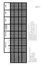
3-1.7 Table 3-1.7 illustrates the alarm and shutdown require-
ments of NFPA-110, NFPA99 and CAN/CSA-C282-M89 and
compares the features of the A900 series controls to those
requirements.
3-2 A901.
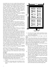
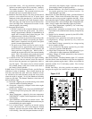
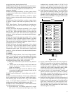
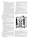
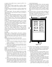
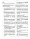
3-2.1 Control / Display Module. The Control / Display Module,
figure 3-2.1, includes the control and test switches, the solid state
logic elements, shutdown and alarm TATTLETALE
®
lights that
make up the generator engine control for a four-cycle engine.
3-2.1.1 Mode Selector Switch, OFF-AUTO-TEST:
(a) OFF; turns off the control system and resets any shutdown
circuits.
(b) AUTO; turns on the engine controls and shutdown circuits.
System is on standby waiting for a contact closure to start
engine.
(c) TEST; turns on the engine controls and shutdown circuits.
A start signal is applied to the automatic control and the
engine start sequence begins.
3-2.1.2 Lamp Test Pushbutton: Tests the lights on the A901
module.
3-2.1.3 Alarm Silence Pushbutton: Turns off any audible alarm
that is connected to the Local or Remote Audible Alarm Relays.
The indicating light will remain on as long as the condition
exists. If the Alarm Silence pushbutton is not operated, the
audible alarm will turn off when the alarm contact clears.
3-2.1.4 The A901 SELECTRONIC
®
Control Module includes
the following engine control features:
(a) Cycle crank circuit; will crank the engine for 15 seconds
then rest for 15 seconds until the engine starts. The
crank/rest time can be selected for either 10, 15, 20, 25 or
30 seconds. If the engine false starts, goes above crank
disconnect speed then drops below that speed, the control
will rest for a fixed 10 second period before cranking again.
(b) Crank Disconnect Speed Switch; this circuit detects
engine speed and terminates cranking when engine speed
rises above the speed switch setting. The speed switch is
adjustable, 25 Hz to 2000 Hz, and is factory set at 1180
Hz. This would be 600 RPM on an engine with 118 teeth
on the flywheel ring gear.
(c) Auxiliary Crank Disconnect Circuit; this circuit, required by
NFPA-110, is provided as a back up for the Crank
Disconnect Speed Switch. It is operated by an external
switch sensing either speed, generator voltage or some other
variable that could be used to terminate cranking. Either
circuit will disconnect the starter when the engine starts.
Low Water
Temperature
AUTO
OFF
TEST
Loss of Speed
Signal
Lamp Test
Water
Temperature
Low Battery
Voltage
Alarm Silence
High Battery
Voltage
Low Fuel
Level
High Water Temp.
PreAlarm
Battery Charger
AC Failure
Switch
Not In AUTO
Low Oil Pressure
PreAlarm
Oil Pressure
Overspeed
Overcrank
6-1/2 in.
(165 mm)
9-3/4 in.
(248 mm)
Figure 3-2.1
2