


(h) #8 Spare Alarm; operated by an external switch. This
circuit is provided for an additional alarm that may be
required by the user.
(i) #9 Spare Alarm; operated by an external switch. This
circuit is provided for an additional alarm that may be
required by the user.
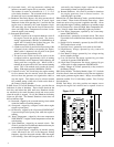
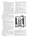
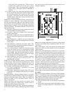
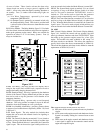
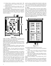
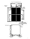
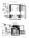
3-6.2 Relay Module. The Relay Module, figure 3-6.2, includes
all of the control, alarm and shutdown relays that are required to
make up the generator engine control. Relays are available for
operation on either 12 or 24 volt battery systems. Three (3)
relays are included for:
3-6.2.1 Fuel Relay; this relay provides two outputs, one to
energize the engine fuel solenoid and a separate circuit to
energize the battery charging alternator field.
3-6.2.2 Shutdown Relay; this relay is operated by the shutdown
circuits of the Control / Display Module and provides an output
that can be used to trip the generator circuit breaker on an
emergency shutdown.
3-6.2.3 Local Audible Alarm Relay; provides a contact closure
to operate a local audible alarm as required by NFPA- 110, Level
1 and Level 2.
3-6.3 Status Signals. The relay module also includes three
outputs that can be used with external circuits for signaling or
control functions.
3-6.3.1 The Control On function at terminal 12 is on (closed to
negative) as long as the Mode Selector Switch is in either Auto
or Test. When the Mode Selector is turned Off, the Control On
signal is open. This can be used to signal switch position or to
reset an external circuit when the Mode Selector is turned Off.
3-6.3.2 The System Ready signal at terminal 13 is on (closed
to negative) as long as the Mode Selector Switch is in either
Auto or Test and no shutdown TATTLETALE
®
circuit is
latched on. This can be used to signal that the generator
engine is ready to automatically start or is running in Test.
3-6.3.3 The Control On function at terminal 14 is on (closed to
positive) as long as the Mode Selector Switch is in either Auto
or Test. When the Mode Selector is turned Off, the Control On
signal is open. This can be used to signal switch position or to
reset an external circuit when the Mode Selector is turned Off.
3-7 A903-2.
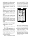
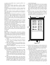
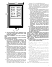
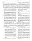
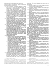
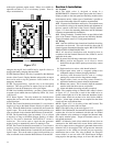
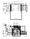
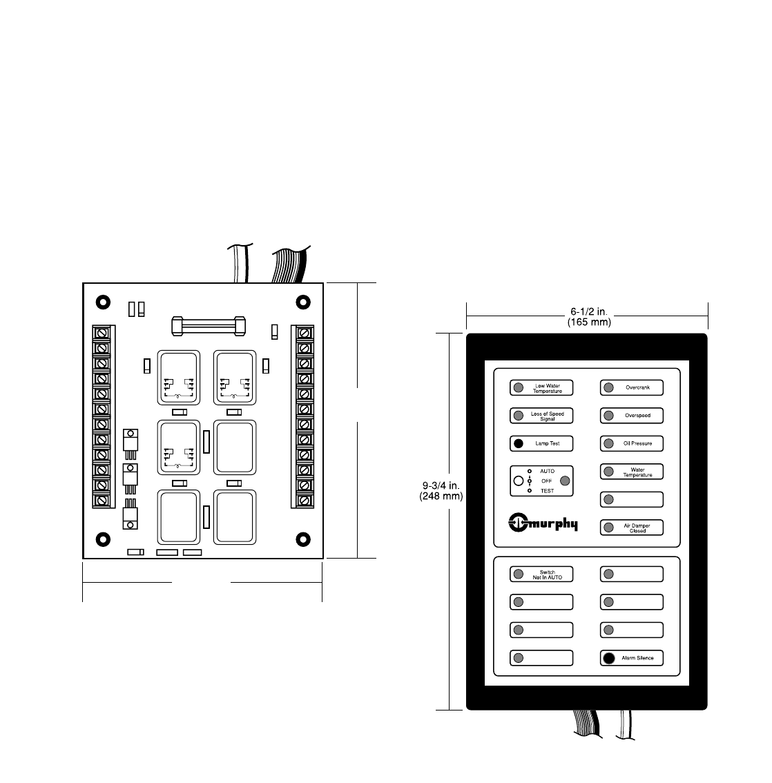
3-7.1 Control / Display Module. The Control / Display Module,
figure 3-7.1, includes the control and test switches, the solid
state logic elements, shutdown and alarm TATTLETALE
®
lights
that make up the generator engine control for a two-cycle
engine. This module is the same as Model A901-2 except 6 of
the alarm circuits are un-labeled. This allows the customer to
specify labels other than those recommended in NFPA-110.
This model has shutdown and alarm circuits labeled to meet the
requirements of NFPA-110, Level 2.
3-7.1.1 Mode Selector Switch, OFF-AUTO-TEST:
(a) OFF; turns off the control system and resets any shutdown
circuits.
(b) AUTO; turns on the engine controls and shutdown
circuits. System is on standby waiting for a contact
closure to start engine.
(c) TEST; turns on the engine controls and shutdown circuits.
A start signal is applied to the automatic control and the
engine start sequence begins.
3-7.1.2 Lamp Test Pushbutton: Tests the lights on the A- 903-2
module.
3-7.1.3 Alarm Silence Pushbutton: Turns off any audible alarm
that is connected to the Local or Remote Audible Alarm Relays.
The indicating light will remain on as long as the condition
exists. If the Alarm Silence pushbutton is not operated, the
Figure 3-7.1
12
DC24V
3A Fuse
1A
4
5
6
7
8
9
16
17
18
19
20
21
22
23
24
25
DC24V
DC24V
6-1/4 in.
(159 mm)
4-1/2 in.
(114 mm)
Figure 3-6.2