


current rating that is equal to or greater than the forward current
that the coil draws to operate. For example, a relay less than 1 A,
use a 1 A diode since they are readily available. The wiring
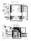
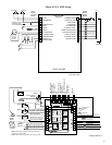
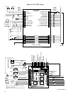
shown in Figures 4-2.3.1, 4-2.3.2 and 4-2.3.3 have examples of
the places that a reverse diode is required.
4-3 Crank Disconnect.
4-3.1 A magnetic pickup is recommended to supply the speed
signal for the A900 series primary crank termination circuit and
for the overspeed switch. This pickup will be mounted in the
flywheel housing in line with the ring gear on the flywheel and
wired to the A900 using either a twisted pair or a shielded cable
to reduce the possibility of electrical noise pickup in the wiring.
4-3.1.1 The tachometer terminal, of the battery charging
alternator, may be used for the speed signal but a broken drive
belt will disable this source and some alternators have electrical
noise which will cause the speed switches to operate at speeds
well below the desired RPM.
4-3.2 An auxiliary crank disconnect circuit, required by
NFPA-110, is provided in the A900. Any signal that detects
when the engine is running and provides a contact closure
between Terminals 4 and 16 can be used. This circuit
terminates cranking even if the speed signal fails. The “Loss
Of Speed” shutdown / alarm on the A900 will indicate if the
speed signal is lost while the engine is running by either
shutdown of the engine or operation of the alarm circuit.
“Loss Of Speed” alarm will only operate if the auxiliary crank
disconnect circuit is used. Provision is also made for a second
N.C. contact between Terminals 17 and 18 to interrupt the
output to the auxiliary starter solenoid. This would disconnect
cranking even if both crank disconnect circuits in the A900
should fail. If this contact is not provided, you must jumper
Terminals 17 and 18 for the start signal to reach the auxiliary
starter solenoid. A voltage sensing relay wired to one output
phase of the generator is one way to provide both of these
contacts.
4-4 Pre-operational Check-out.
4-4.1 After installation is complete, it is necessary to make
some adjustments to the A900 SELECTRONIC
®
Control before
the system is operational. All shutdown and alarm circuits also
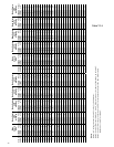
should be tested. Table 4-4.1 lists the standard factory setting of
the adjustable functions on the A900 series control. To
determine if the frequency of the speed switches must be
changed, calculate the required setting using the following
formulas:
Refer to Table 4-4.1 to determine if the speed switch settings are
below the factory settings listed. If required frequency will be
higher than the standard, increase the setting before proceeding.
Turn The Crank Disconnect Set and Overspeed Set pots
clockwise to increase setting. The adjustments are 20 turn
controls without stops at either end.
4-4.1.1 Be sure to have a fully charged battery to do these tests.
Low battery voltage can cause improper results during the tests.
4-4.1.2 The “Air Damper Closed” alarm on A900 series for 2
cycle engines can be actuated by either an internal circuit that
senses the output to the overspeed relay, from the “Overspeed”
shutdown circuit or by an external switch wired to terminal 34
of the Control / Display Module. The “Air Damper Closed”
switch, Table 4-4.1 must be turned On for internal sensing and
Off for external switch. This circuit is a Spare alarm on A900
for 4 cycle engines and the switch must be turned Off to
prevent this circuit from operating with the “Overspeed”
shutdown.
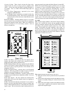
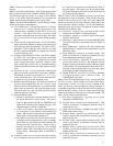
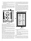
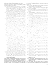
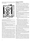
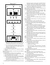
4-4.1.3 All of the adjustments and controls shown in Table 4-4.1
are located on the rear of the control/display module. See Figure
4-4.1.3. Each light and switch is labeled for ease of
identification. The LED's are supplied as an aid in installation
and troubleshooting of the A900.
4-4.2 Crank Disconnect Speed Setting; to set this speed switch,
proceed as follows:
(a) Disconnect the run solenoid wire from terminal 6 on the
Relay Module.
(b) Check engine to be sure it is safe to crank.
(c) Be sure Mode Selector switch is in OFF position.
(d) Connect battery cables to a fully charged cranking battery.
(e) Turn Mode Selector switch to TEST position and watch
the lights on the A900 control module back panel.
1. The engine should start cranking and the “Fuel Relay”,
“Crank Relay”, and “Pickup Present” lights turn on.
2. If engine does not crank, check the lights. If green
light next to Mode Selector Switch on front panel is
not on, check the DC power input wiring and fuse.
3. If green light, “Fuel Relay” and “Crank Relay” lights
are on, check wiring from A900 Terminal 18 to
auxiliary start solenoid and than on to the starter on
engine.
4. With engine cranking, check “Pickup Present” light. It
must be on. If off, check the wiring to magnetic
pickup and check gap between pickup face and ring
gear.
5. If “Crank Disconnect Speed” light comes on and
cranking stops, setting of Crank Disconnect Switch is
still to low. Turn Mode Selector switch OFF and turn
crank disconnect adjustment clockwise 1 or 2 turns
and repeat test.
19
No. of Gear Teeth x RPM set points
60
Set point
frequency in HZ
Pulley ratio x No. of Alternator Poles x RPM set points
60
Set point
frequency in HZ
=
=
Function
Standard
Setting
Adjustment
Range
Adjustment
Type
Crank/Rest
Time
15
seconds
10, 15, 20, 25
and 30 Seconds
Switch
Overcrank 3 cranks
1, 2, 3, 4, 5, 6 and
No overcrank
Switch
Crank
Disconnect
1180 Hz
Turn CW
to increase
25 to 2 KHz
Overspeed
3894 Hz
Turn CW
to increase
300 to 10 KHz
Cooldown
OFF
Fixed 5 minute ON-OFF switch
Loss of speed
Signal
Shutdown
Shutdown or
Alarm
Switch
ON with
Overspeed
shutdown
Internal switch ON
External switch OFF
Switch
Table 4-4.1
OR
Air Damper Closed
Alarm on 2 Cycle
Engines only