


PAGE 36 — TLG-12SPX — PARTS AND OPERATION MANUAL (STD) — REV. #4 (03/08/05)
Motors and motor-driven equipment draw much greater current
for starting than during operation.
An inadequate size connecting cable which cannot carry
the required load can cause a voltage drop which can burn
out the appliance or tool and overheat the cable.
When connecting a resistance load such as an
incandescent lamp or electric heater, a capacity of up
to the generating set’s rated output (kW) can be used.
When connecting a fluorescent or mercury lamp, a
capacity of up to the generating set’s rated output (kW)
multiplied by 0.6 can be used.
When connecting an electric drill or other power tools,
pay close attention to the required starting current
capacity.
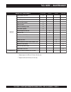
daoLyBrotcaFrewoP.01elbaT
daoLfOepyTrotcaFrewoP
srotomnoitcudniesahp-elgniS57.0-4.0
tnecsednacni,sretaehcirtcelE
spmal
0.1
spmalyrucre
m,spmaltnecseroulF9.0-4.0
noitacinummoc,secivedcinortcelE
tnempiuqe
0.1
slootrewopnommoC8.0
The power factor of this generator is 1.0. See Table 10.
below when connecting loads.
TLG-12SPX —LOAD APPLICATION
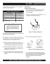
NOTE
If output (kVA) is not given on the
equipment nameplate, approximate
output may be determined by
multiplying voltage by amperage by
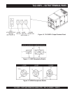
NEGATIVE
POSTIVE
BATTERY
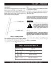
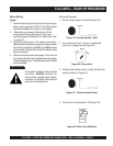
2. Connect the negative battery cable (BLACK) to the
negative post on the battery (Figure 17).
Figure 17. Battery Connections
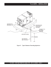
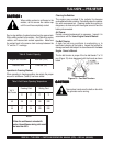
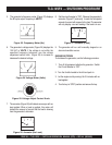
3. Close all engine enclosure doors (Figure 18).
Figure 18. Engine Enclosure Doors
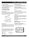
4. Ground any equipment necessary using the ground
lug on the generator, and the GFCI ground plug located
on the output terminal panel, next to the throttle lever.
See Figure 8, page 29 for proper grounding
techniques.
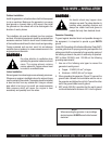
Before Starting
Generator and Control Panel
1. Be sure to disconnect the electrical load and switch
the circuit breaker to the “OFF” position prior to
starting the engine.