


SP 1 SAW CE— OPERATION AND PARTS MANUAL — REV. #3 (06/09/08) — PAGE 29
MQ STREET PRO 1 CE SAW — OPTIONAL WATER TANK
1
6
8
7
9
11
12
10
13
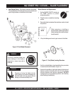
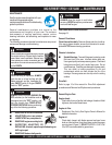
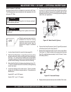
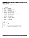
WATER TANK KIT (OPTION)
1. Locate all parts listed in the parts list (see page 45).
2. Slide the Tank Shelf (item 1, Figure 25) over the top of the
engine so the recoil starter fits through the large opening in
the shelf. The recoil starter handle must be accessible
through this opening. Ensure the recoil starter handle can be
pulled without binding or interference with the shelving.
3. Mount the Tank Shelf to the frame using hardware items 7, 9,
11, and 13 to attach the shelf to the frame utilizing existing
slots in the frame.
4. Locate the Spacers for the tank mount. This kit provides
spacers for two different engine options. The spacers are
identified as:
Honda 9HP - use 2-3/8" spacer
Honda 13HP - use 1-1/2" spacer
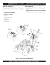
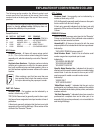
An optional water tank kit is available for use with the SP1 Saw.
The following steps are instructions for the assembly of the kit
onto your SP1 Saw.
Make certain all bolts securing the kit to the saw are tight
before operating the saw.
CAUTION
DO NOT use a water tank larger than 5 gallons (18.95 liters)
with this kit.
CAUTION
NOTE
While the optional water tank kit is
excellent for short-run cutting
operations, the use of a pressurized,
continual water source may be
preferred for longer or sustained
cutting.
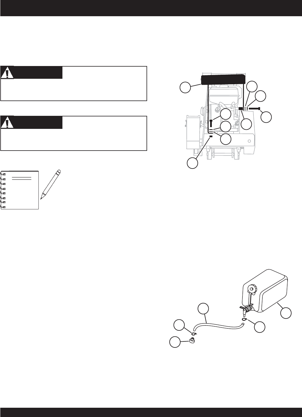
Figure 25. Water Tank Kit (Option)
5. After determining the correct spacer length, place the spac-
ers (item 12, Figure 25) betweem the engine block and the
tank shelf bracket and secure the assembly with the 3/8"
hardware (items 6, 8, and 10). Use the appropriate length bolt
(item 6) for your application.
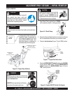
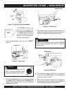
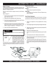
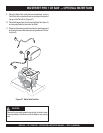
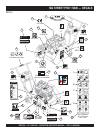
6. Connect the Swivel Connector (item 5, Figure 26) to one end
of the hose (item 3) with clamp (item 2).
7. Remove the hard plastic tube from the valve on the Water
Tank (item 14). Slide this tube into the open end of the hose
(item 3) to a depth of approximately 1inch (25.4mm). Fasten
with clamp (item 2).
Figure 26. Hose and Clamps
8. Replace the hard plastic tube back into the Water Tank valve.
2
5
2
3
14