


SP 1 SAW CE— OPERATION AND PARTS MANUAL — REV. #3 (06/09/08) — PAGE 15
MQ STREET PRO 1 CE SAW — CONTROLS & COMPONENTS
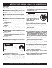
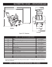
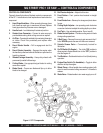
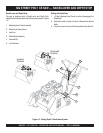
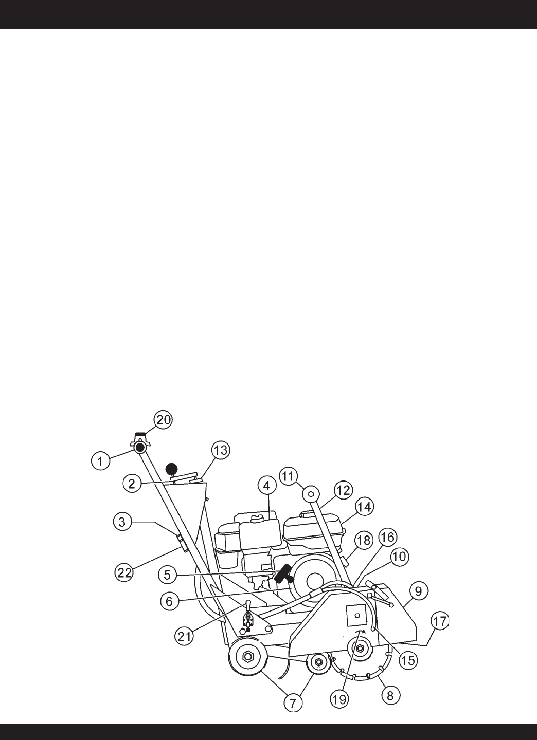
Figures 4 shows the location of the basic controls or components
for the SP 1. Listed below is a brief explanation of each control or
component.
1. Hand Grips/Handlebar – When operating the saw, place
both hands on each grip to maneuver the saw. Replace
hand grips when they become worn or damaged.
2. Handle Lock – Lock blade depth to desired position.
3. Garden Hose Connecter – Connect to water source to
provide blade cooling while cutting concrete or asphalt.
4. Air Filter – Prevents dirt and debris from entering the engine
air intake. Check filter periodically and replace when
necessary.
5. Recoil Starter Handle – Pull to engage and start the
engine.
6. Recoil Starter Assembly – Engages the engine when
the handle is pulled and rewinds the starter rope when the
handle is released.
7. Wheels/Carriage Assembly – Heavy-duty wheels with
permanently sealed ball bearings.
8. Cutting Blade – Use appropriate type blades for cutting
concrete or asphalt.
9. Blade Guard – Covers saw blade and flips up to allow
blade to be changed.
CONTROLS & COMPONENTS
Figure 4. SP 1 Components
10. Belt Tension Adjuster – Adjusts belt tension.
11. Front Pointer – Front pointer wheel assists in straight
tracking.
12. Front Pointer Arm – Stows up for storage and pivots down
for use.
13. Cutting Depth Adjuster – turn operating crank clockwise
or counter-clockwise to adjust the cutting depth up or down.
14. Fuel Tank – Use unleaded gasoline. Do not overfill.
15. Blade Coolant System – Provides cooling water to blade
during cutting operations.
16. V-Belt Cover – Remove this cover to gain access to the V-
belts. NEVER operate the saw with this cover removed.
17. Spindle Grease Zerks – Conveniently located for
lubrication.
18. On/Off Switch (On Engine) – Turn to the "ON" position to
allow engine to be started and turn to the "OFF" position to
shut the engine off.
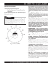
19. Tool Rotation – Rotational direction of tool (blade) during
operation.
20. Engine Stop Switch (On Handlebar) – Toggle in either
direction to stop the engine.
21. Wheel Clamp – Move handle down making contact with
wheel to avoid unwanted rolling movement. Lift handle to
release.
22. Water Valve – Rotate handle to turn water supply on or off.