


PAGE 70 — INDUSTRIAL GENERATOR SETS — APPLICATION & INSTALLATION MANUAL — REV. #4 (09/07/07)
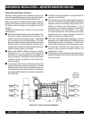
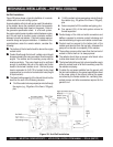
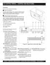
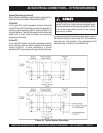
Figure 31. Typical Inner Control Box Panel
DC CONTROL WIRING — CONTROL BOX BACK PANEL
Control Box
The control box contains the following:
Digital Control Module
There are several digital control modules available for MQ
Power industrial generator sets. Reference your supplied
digital control manual for detailed information.
Control Box Back Panel Components
Figure 31 shows the components found in the Control Box back
panel. The actual configuration of these components may vary
with each control module model depending on the desired
specifications and DC controls used. However. the typical
contents are as follows:
z
Standard Electronic Governor
z
TB1 Terminal Block
z
Control Relays
z
Fuses
The definitions below describe the components
of the "Control Box" back panel
Electronic Governor (Standard) – This
electronic speed control exhibits fast and
precise response to transient load
changes. When used in conjunction with a
proportional electric actuator, the governor
offers closed loop governing.
Either isochronous or droop governing
modes can be selected. The engine's idle
speed is variable and selected by a simple
switch closure. Engine exhaust smoke
during start-up can be minimized when the
starting fuel adjustment is optimally set.
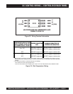
Start Relay (K2) – This relay interfaces
with the engine (75-150kW) and electronic
governor controller (if present) for start and
stop functions of the generator.
Idle Relay (K4) – This optional relay is
installed to interface with the voltage
regulator sensing circuits when the optional
idle switch is used.
Shunt Trip Relay (K5) – This relay optional
relay is installed to trip the main output circuit
breaker under fault conditions. This circuit
can be wired to the genset controller to trip
the breaker or a shutdown condition.
This relay can also be wired to an external
(customer supplied) circuit for external trip
control of the breaker.
Low Coolant Level Relay (K3) – This
relay is installed to interface with the low
coolant level switch to the genset controller.
Relay DIN Rail – This rail holds all the
relays used for DC controls.
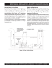
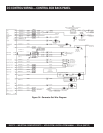
Terminal Block One (TB1) – This terminal
block is used for DC control wiring. See
the generator set wire diagram (Figure 34)
on page 72 for details.
1
2
3
4
5
6
7
8
Control Power Fuse – This fuse protects
terminal block one (TB1) from overcurrent.
Remove this fuse when servicing TB1.