


INDUSTRIAL GENERATOR SETS — APPLICATION & INSTALLATION MANUAL — REV. #4 (09/07/07) — PAGE 39
MECHANICAL INSTALLATION — FUEL SYSTEM (DIESEL)
Diesel Fuel Supply
Consider the following when installing a diesel fuel supply
system:
Fuel supply tank construction, location, installation,
venting, piping, testing, and inspection must comply with
all applicable codes. In addition, see NFPA Standards
No. 30 and No. 37.
Fuel supply tanks must be adequately vented to prevent
pressurization, have provisions for manually draining or
pumping out water and sediment, and have at least a
five percent expansion space to prevent fuel spillage
when the fuel heats up and expands.
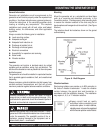
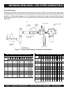
The fuel lift pump, day tank transfer pump, or float valve
seat should be protected from fuel supply tank debris by
a pre-filter or sediment bowl with a 100 to 120 mesh
element.
The supply tank must hold enough fuel to run the genset
for the prescribed number of hours (NFPA No. 110 Class
designation) without refueling. Tank sizing calculation
should be based on the hourly fuel consumption rates
on the genset specification sheet.
For emergency power systems, codes might not permit
the fuel supply to be used for any other purpose, or may
specify a drawdown level for other equipment that
guarantees the fuel supply for emergency power use.
The cetane rating of No. 2 heating oil is not high enough
for dependable starting of diesel engines in extreme cold
weather climates. Therefore, separate supply fuel tanks
for emergency power and building heating systems may
have to be provided.
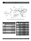
Approved flexible fuel hose must be used for connections
at the engine to prevent damage from genset movement
and vibration.
Diesel fuel lines should be black iron pipe. Cast iron and
aluminum pipe and fittings must NOT be used because
they are porous and can leak.
Galvanized fuel lines, fittings, and tanks SHOULD NOT
be used because the galvanized coating reacts with the
sulfuric acid that forms when the sulfur in the fuel
combines with tank condensation. Such a practice would
result in debris that can clog fuel pumps and filters.
Although copper has been used for diesel fuel lines in
the past, black iron pipe is preferred. Diesel fuel
polymerizes (thickens) in copper tubing during long
periods of standby. This can cause the fuel injectors to
clog.
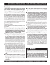
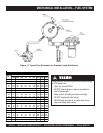
Refer to the engine specification sheet for the maximum
fuel inlet and return restrictions, the maximum fuel flow,
and the fuel consumption. Then refer to Table 10 for the
minimum hose and pipe sizes for connections to a supply
tank or day tank that is relatively close to the set at
approximately the same elevation. Hose and pipe size
should be based on the maximum fuel flow rather than
the fuel consumption
(The maximum fuel flow can be
twice the full-load fuel consumption)
. It is highly
recommended that the fuel inlet and return restrictions
be checked before the set is placed into service.
Separate fuel return lines to the day tank or supply tank
must be provided for each generator set in a multiple-set
installation to prevent the return lines of any idle set from
being pressurized. Also, a fuel return line must NOT
include a shut-off device. Engine damage will occur if
the engine is run when the fuel line is shut off.
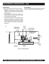
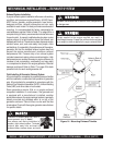
A day tank is required whenever pipe friction and/or supply
tank elevation, either below the fuel pump inlet or above
the fuel injectors, would cause an excessive fuel inlet or
return restriction.
For critical start applications, where gensets are paralleled
or must satisfy emergency start-time requirements, it is
recommended that a fuel tank or reservoir be located
such that the lowest possible fuel level is not less than 6
inches (150 mm) above the fuel pump inlet. This will
prevent air from accumulating in the fuel line while the
genset is in standby, eliminating the period during start-
up when the air has to be purged.
seziSepiPdnaesoHnruteR/ylppuSleuFmuminiM.01elbaT
mumixaM
HPG
wolFleuF
eniLylppuSleuFeniLnruteRleuF
teeF01-0
)serteM3-0(
teeF05-01
)serteM51-3(
teeF01-0
)serteM3-0(
teeF05-01
)serteM51-3(
xelF
esoH
eziS
.D.IepiP
sehcnI
)mm(
xelF
esoH
eziS
.D.IepiP
sehcnI
)mm(
xelF
esoH
eziS
.D.IepiP
sehcnI
)mm(
xelF
esoH
eziS
.D.IepiP
sehcnI
)mm(
51-06.oN
61/5
)9.7(
8.oN
23/31
)3.01(
4.oN
61/3
)8.4(
6.oN
61/5
)9.7(
02-618.oN
23/31
)3.01(
01.oN
2/1
)7.21(
4.oN
61/3
)8.4(
6.oN
61/5
)9.7(
08-1201.oN
2/1
)7.21(
21.oN
8/5
)9.51(
8.oN
23/31
)3.01(
01.oN
2/1
)7.21(
001-1821.oN
8/5
)9.51(
61.oN
8/7
)3.22(
8.oN
23/31
)3.01(
01.oN
2/1
)7.21(
061-10161.oN
8/7
)3.22(
61.oN
8/7
)3.22(
01.oN
2/1
)7.21(
21.oN
8/5
)9.51(
<06161.oN
8/7
)3.22(
61.oN
8/7
)3.22(
21.oN
8/5
)9.51(
21.oN
8/5
)9.51(
thgiehtfilleuflaminimdna,sgnittif°09owt,sgnittifthgiartsruofnodesaB