


LT12DAB LIGHT TOWER • OPERATION MANUAL — REV. #0 (06/03/11) — PAGE 19
CONTROL PANEL
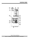
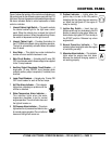
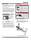
Figure 5 shows the location of the controls and indicators on
the control panel for the different engines used with the LT12
light tower. Service the equipment as needed depending on
the alarm indicated. Below is a brief explanation of each
control or indicator.
1. Internal Cabinet Light Switch — This switch controls
the internal cabinet light for the light tower control
panel. When the cabinet door is raised, the light will
automatically come on. When the cabinet door closes,
the switch is depressed and the light turns off.
2. Internal Cabinet Light — Provides illumination for
the LT12DAB control panel during nighttime operation.
The light is automatically activated when the cabinet
door is raised.
3. Hour Meter — This digital hour meter indicates the
number of hours machine has been in use.
4. Main Circuit Breaker — A double-pole 30 amp, ON/
OFF circuit breaker which allows voltage to be supplied
to the 15 amp breakers.
5. Auxiliary Output Receptacle Circuit Breaker — A
single-pole, 15 amp, ON/OFF circuit breaker which
protects auxiliary output receptacle (if installed) from
overload.
6. Lamp Circuit Breakers — A single-pole, 15 amp, ON/
OFF circuit breaker for each of the four lamps.
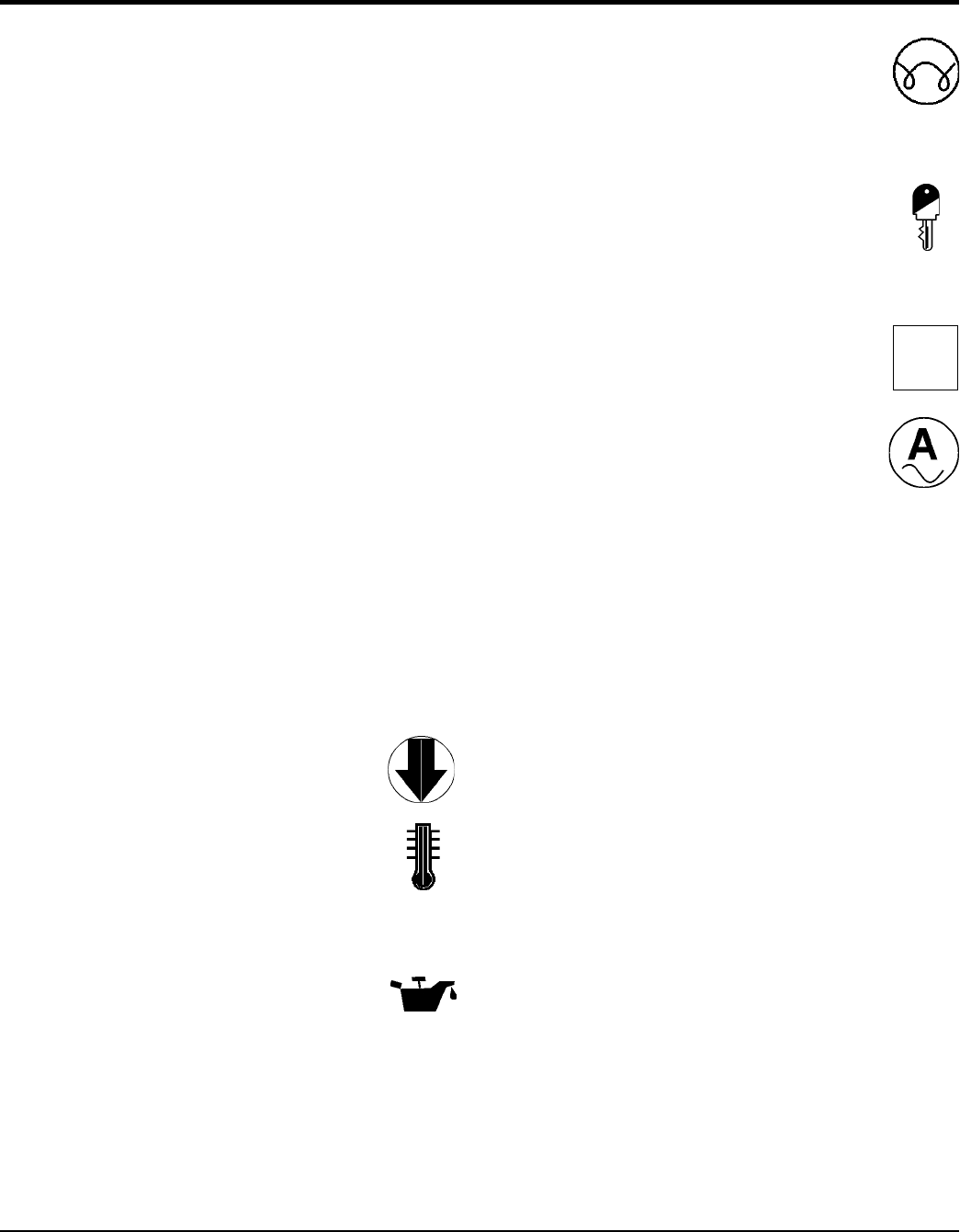
7. Air Filter Alarm Indicator — This indicator
lights when a blockage or problem with the
air filter is detected.
8. Water Temperature Alarm Indicator —
This indicator lights when the water
temperature becomes to hot for normal
engine operation. The unit will shut down and
the light will remain on.
9. Oil Pressure Alarm Indicator — This alarm
lights when the oil pressure has fallen too low
for normal engine operation The unit will shut
down and the light will remain on.
10. PreHeat Indicator — Lights when the
ignition key is turned to the ON position
indicating that the glow plugs are warming
up. When the light goes off, the engine is
ready for starting..
11. Ignition Key Switch — Insert key into
ignition switch and turn clockwise to the ON
position to warm the glow plugs. When pre-
heat indicator light goes OFF, turn the key to
the START position. Release key when
engine starts.
12. Normal Operation Indicator — This
indicator (green lamp) lights when the engine
is functioning normally.
13. Alternator Alarm Indicator — This indicator
lights when the engine has shut down
because the electrical charging system is
not working properly.
OK