


PAGE 28 — DCA-45USI — OPERATION AND PARTS MANUAL (STD) — REV. #2 (04/22/05)
DCA-45USI — GENERATOR OUTPUTS
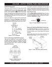
GFCI Receptacle Load Capability
The load capability of the GFCI receptacles is directly re-
lated to the voltage being supplied at either the output termi-
nal lugs or the 3 twist lock auxilliary receptacles.
Tables 8 and 9 show what amount of current is available at
the GFCI receptacles when the UVWO terminals and twist
lock receptacles are in use. Be careful that your load does
not to exceed the available current capability at the recep-
tacles.
ytilibapaCdaoLelcatpeceRICFG.8elbaT
esUniWK
)9636SC(kcoL-tsiwT
tnerruCdaoLelbaliavA
)SPMA(
V021/042Ø1
AMENxelpuDICFG
V021R02-5
060
8.85elcatpecerre
pspma5
6.75elcatpecerrepspma01
4.65elcatpecerrepspma51
2.55elcatpecerrepspma02
ytilibapaCdaoLelcatpeceRICFG.8elbaT
esUniAVK
)slanimreTOWVU(
tnerruCdaoLelbaliavA
)SPMA(
V084/042Ø3
AMENxelpuDICFG
V021R02-5
280
8.77elcatpecerreps
pma5
7.37elcatpecerrepspma01
5.96elcatpecerrepspma51
4.56elcatpecerrepspma02
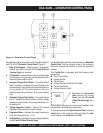
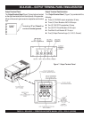
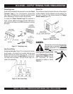
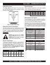
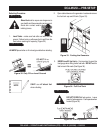
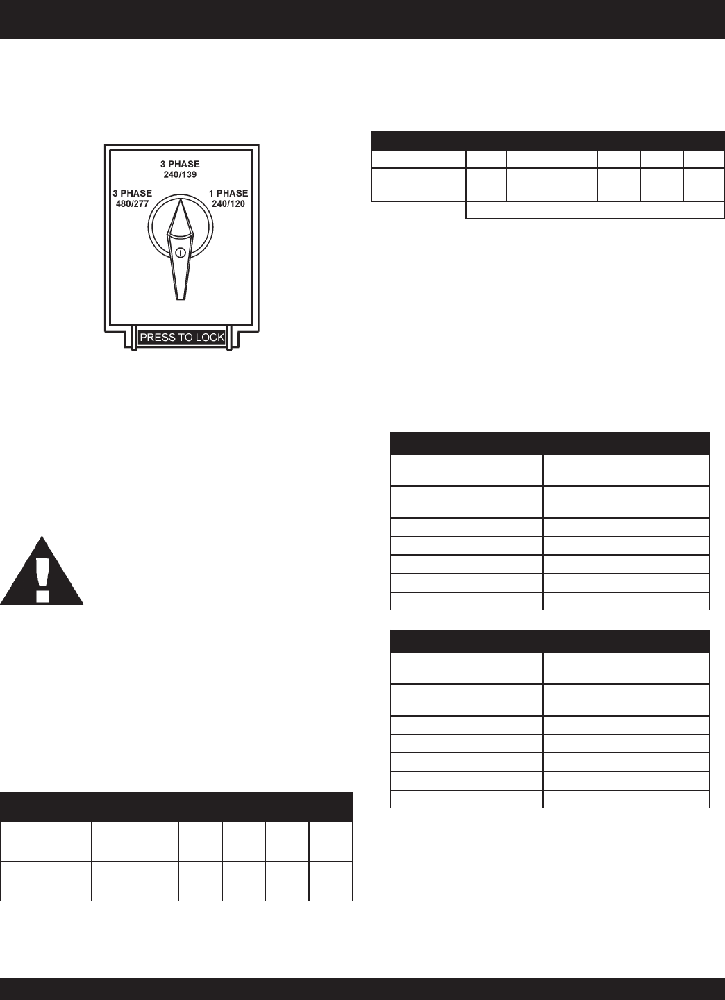
Voltage Selector Switch
The
voltage selector
switch (Figure 15) is located above
the UVWO Hard Wire Hook-up Panel. It has been provided
for ease of voltage selection.
CAUTION:CAUTION:
CAUTION:CAUTION:
CAUTION:
NEVER change the position of the
voltage
selector switch
while the engine is running.
ALWAYS place circuit breaker in the open
position before selecting voltage.
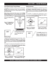
Voltage Selector Switch Locking Button
The voltage selector switch has a locking button to protect
the generator and load from being switched while the engine
is running. To lock the voltage selector switch,
press
and
hold
the
red button
located at the bottom of the switch.
Figure 15. Voltage Selector Switch
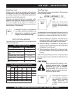
Generator Amperage
Table 7 describes the generator’s current output capability
for both 1Ø-phase and 3Ø phase applications.
elbaliavAsegatloV.6elbaT
esahPeerhT
)elbahctiwS(
V802V022V042V614V044V084
esahPelgniS
)elbahctiwS(
V021V721V931V042V452V772
sgnitaRerepmArotareneG.7elbaT
JSU54-ACDWkAVkV021V802V042V084
esahPelgniS62A/N2xA801A/NA801A/N
*esahPeerhT6354A/NA521A801A45
8.0=rotcaFrewoP*
Generator Output Voltages
A wide range of voltages are available to supply voltage for
many different applications. Voltages are selected by using
the
voltage selector
switch
(Figure 14). To obtain some of
the voltages as listed in Table 6 (see below) will require a
fine adjustment using the
voltage regulator
(VR)
control
knob
located on the control panel.