


PAGE 26 — DCA-45USI — OPERATION AND PARTS MANUAL (STD) — REV. #2 (04/22/05)
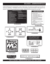
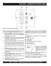
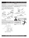
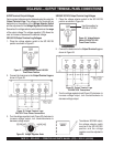
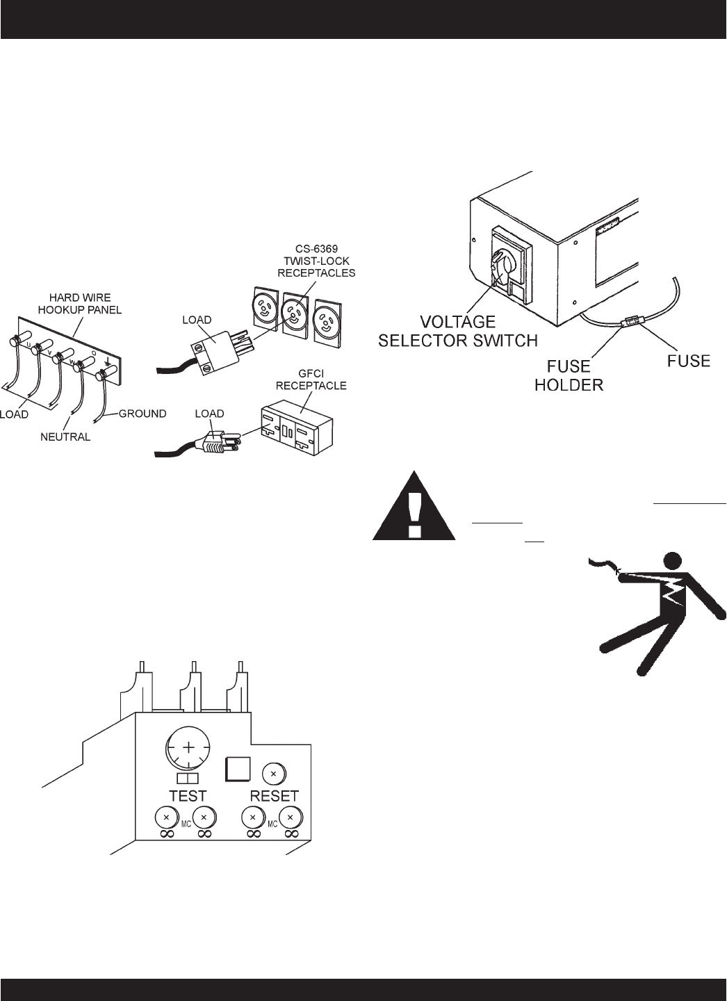
Figure 12. Connecting Loads
Connecting Loads
Loads can be connected to the generator by using the
Output
Terminal Lugs
or the convienience receptacles
(See Figure 12). Make sure to read the operation manual
before attempting to connect a load to the generator.
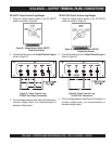
To protect the
Output Terminal Lugs
from overload, a
3-pole, 110 amp,
main
circuit breaker is provided. Make sure to
switch
ALL
circuit breakers to the OFF position prior to starting
the engine.
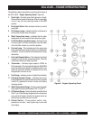
DCA-45USI — OUTPUT TERMINAL PANEL FAMILIARIZATION
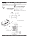
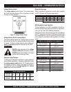
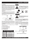
Over Current Relay
An
over current relay
(Figure 13) is connected to the main
circuit breaker. In the event of an overload, both the circuit
breaker and the over current relay may trip. If the circuit
breaker can not be reset, the
reset button
on the over cur-
rent relay must be pressed. The over current relay is lo-
cated in the control box.
Figure 13. Over Current Relay
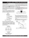
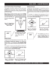
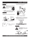
Blower Fan
This unit has an intake fan located at the rear of the machine
to draw outside air into the cabinet to cool the engine. The
fan has a 10 amp AC fuse located beneath the
Voltage
Selector Switch
(Figure 14).
This fuse has current running through it any
time the engine is operating.
THIS FUSE
IS NOT connected to the main circuit
breaker OF the generator. Attempting to
replace the fuse with the engine
and/or generator operating could
result in
electrocution
and
severe
bodily harm
. ALWAYS turn the
unit completely off before
attempting to replace or handle
THIS fuse
DANGER:
Figure 14. Blower Fan Fuse