


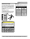
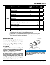
GENERATOR START-UP PROCEDURE (MANUAL)
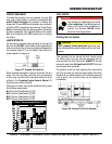
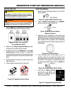
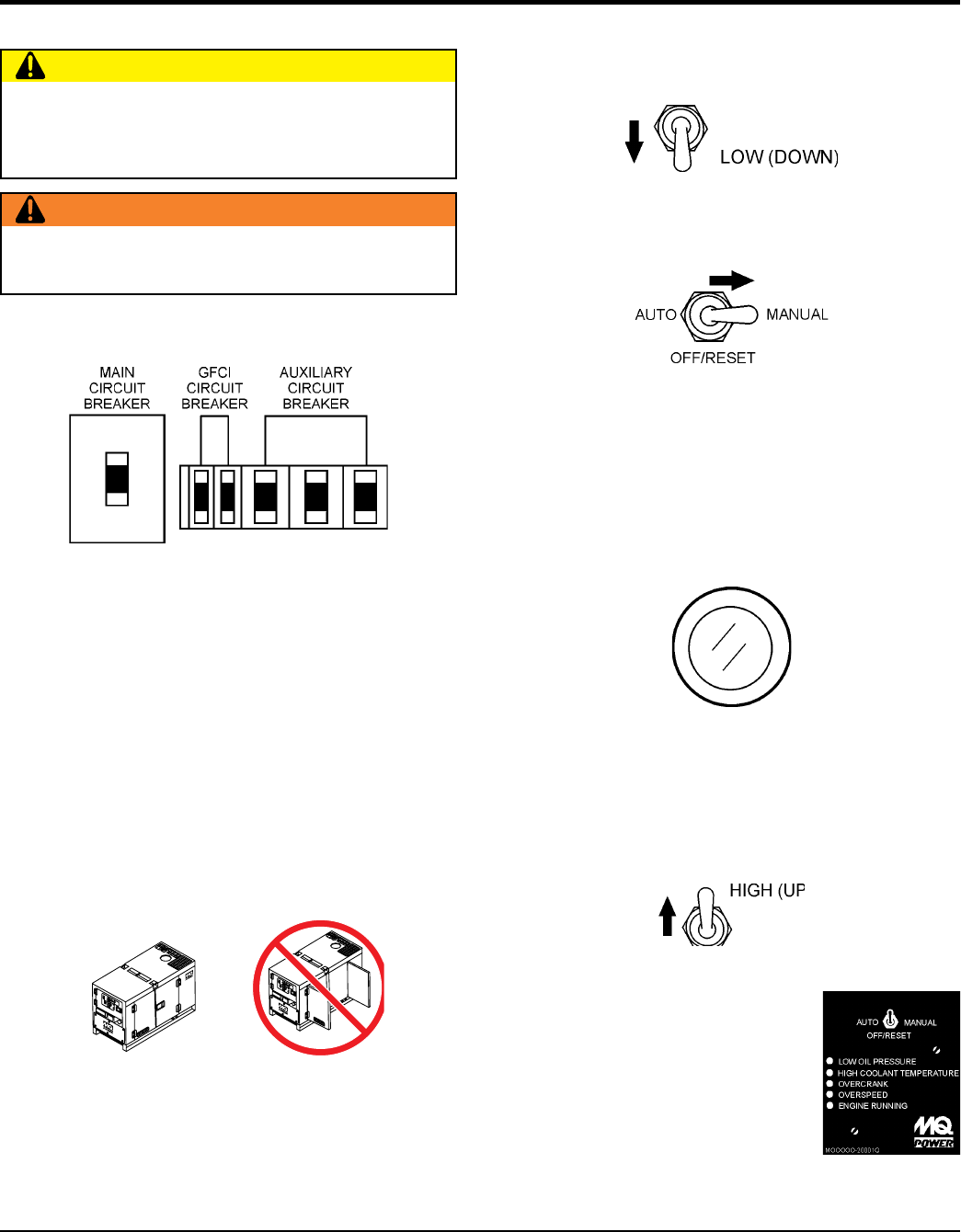
1. Place the circuit breakers (Figure
35) in the position prior to starting the engine.
Figure 35. Main, Aux. and GFCI
Circuit Breakers (OFF)
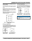
2. Make sure the has been
configured for the desired output voltage.
3. Connect the load to the receptacles or the output
terminal lugs as shown in Figure 10. These load
connection points can be found on the output terminal
panel and the output terminal panel’s hard wire hookup
panel.
4. Tighten terminal nuts securely to prevent load wires
from slipping out.
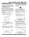
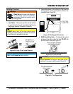
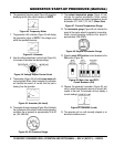
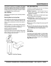
5. Close all engine enclosure doors (Figure 36).
Figure 36. Engine Enclosure Doors
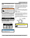
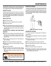
The engine’s exhaust contains harmful emissions.
when operating.
Direct exhaust away from nearby personnel.
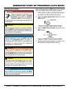
manually start the engine with the
auxiliary circuit breakers in the (closed) position.
INCORRECT
CORRECT
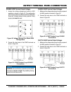
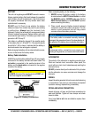
1. Place the engine speed switch (Figure 37) in the LOW
(down) position.
Figure 37. Engine Speed Switch (Low)
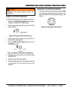
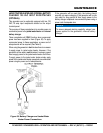
2. Place the in the
position to start the engine (Figure 38).
Figure 38. MPEC Control Switch
(Manual Position)
3. Depending on the temperature of the coolant (cold
weather conditions), the pre-heat lamp (Figure 39) will
light (ON) and remain on until the pre-heating cycle has
been completed. After completion of the pre-heating
cycle, the light will go OFF and the engine will start up
automatically.
Figure 39. Pre-Heat Button
4. Once the engine starts, let the engine run for 1-2
minutes. Listen for any abnormal noises. If any
abnormalities exist, shut down the engine and correct
the problem. If the engine is running smoothly, place
the engine speed switch (Figure 40) in the (up)
position.
Figure 40. Engine Speed Switch (High)
5. Verify that the engine running
status LED on the MPEC unit
(Figure 41) is (lit) after the
engine has been started.
Figure 41. Engine Running LED (ON)